

Dust collector air-to-cloth ratio is the actual gas flow through the filtering system divided by its active filtration area. It is expressed as a velocity, such as metres per minute or actual cubic feet per minute per square foot of media. Calculate it using the operating flow and available area, then select an acceptable value from the dust characteristics, cleaning method, media, and demonstrated application performance. A low purchase price or a large-looking housing does not establish adequate filter area. The calculation is simple; defining the correct inputs and confirming their suitability is the important engineering work.
Write the calculation with consistent units
Use the relationship v = Q / A, where v is filtration velocity, Q is actual volumetric gas flow, and A is active filter area. Rearranging gives A = Q / v when estimating the area required for a selected velocity. Keep the time basis consistent. If flow is in cubic metres per hour and velocity is in metres per minute, divide the hourly flow by sixty before calculating area. Document the convention so a later reviewer does not confuse an hourly ratio with a per-minute value.
For an illustrative calculation, assume an actual flow of 6,000 cubic metres per hour and a trial velocity of 1 metre per minute. The flow becomes 100 cubic metres per minute, so the calculated area is 100 square metres. These are teaching inputs, not a recommended velocity or a YIYI product specification. A project must justify the selected velocity for its material and operating conditions before treating the calculated area as a purchase requirement.
The EPA baghouse and filters cost-manual chapter explains filtration ratio selection and the importance of application conditions. Historical tables are useful reference material, but their values are not universal guarantees and should not replace a current application review.
Use actual flow at the collector
A fan catalogue flow, a nominal conveying flow, and the gas flow actually reaching the collector may differ. Define normal, maximum, minimum, and transient operating cases. Include simultaneous extraction points, leakage or introduced air, and relevant temperature and pressure conditions. If gas quantity is reported at standard conditions, convert it to the specified actual collector conditions using a consistent gas basis and appropriate process data.
Avoid adding unrelated design margins repeatedly without recording them. A margin applied to source airflow, another applied to the fan, and a third applied to the ratio can obscure the real duty. Separate measured demand, justified allowance, and proposed equipment capacity. This makes it possible to compare two supplier offers without unknowingly comparing different airflow assumptions.
Read the dust collector system design guide for the wider system context. The present article addresses filtration-area loading; duct transport velocity, hood capture, fan selection, and explosion protection remain separate parts of the complete design.
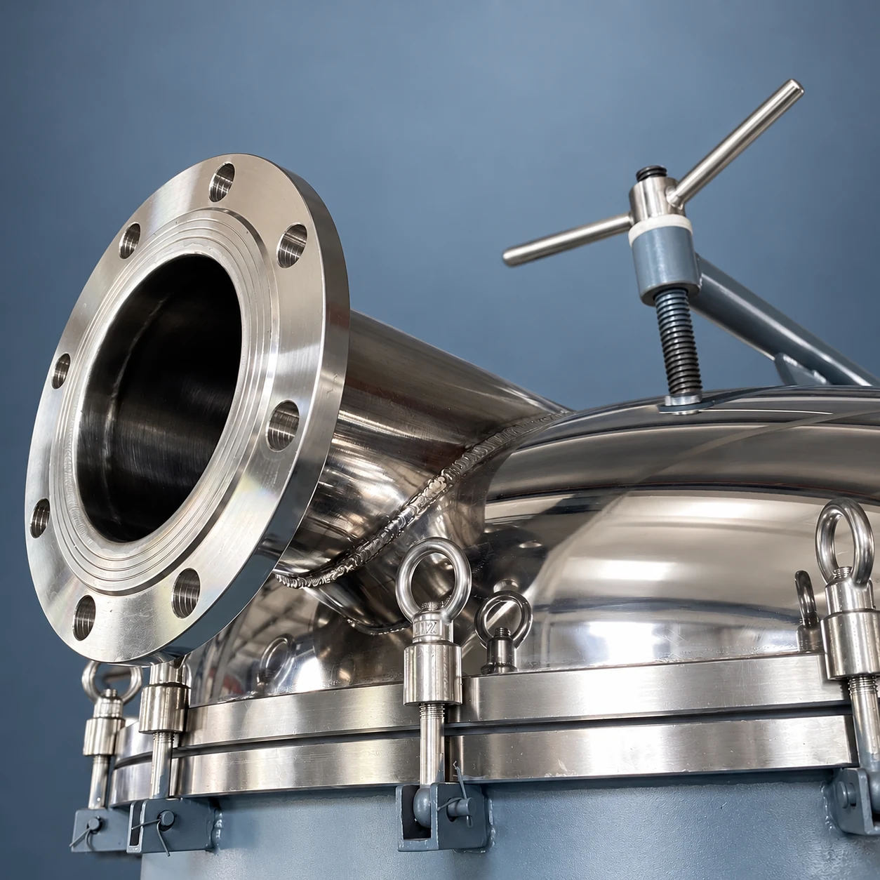
The referenced product photograph illustrates an exterior housing connection. It does not reveal filter area, the installed media, the internal flow path, or rated collection performance. Those must come from the selected configuration’s drawings and application documentation.
Distinguish gross area from area available in service
Gross area is the installed filtration area. Active or net area is the area available to filter the gas for the operating case under review. If a compartment is taken offline while the remaining system continues to operate, the available area falls and the filtration velocity rises at unchanged flow. State explicitly whether a quoted ratio uses gross area or net area. Otherwise, two apparently identical ratios may describe different equipment duties.
For an illustrative system with 120 square metres installed, suppose 20 square metres become unavailable during an agreed operating condition. At 100 cubic metres per minute, the gross-area calculation is about 0.83 metres per minute, while the active-area calculation is 1 metre per minute. Both numbers are mathematically correct; only the second represents that defined reduced-area condition. Neither establishes whether the chosen velocity is suitable for the dust.
The definition of unavailable area depends on the collector and cleaning arrangement. Do not automatically subtract a compartment from every pulse-cleaned configuration. Obtain the supplier’s explanation of filtering and cleaning states, and identify any duty that requires operation during maintenance. Include blocked, blinded, or damaged elements in troubleshooting because effective usable area may deteriorate even when the installed element count stays unchanged.
Confirm how element area was determined
For a simple cylindrical filtering surface, an illustrative area calculation uses circumference multiplied by active length. With diameter D and active length L in consistent units, lateral surface area is πDL. Sum the active surfaces specified by the actual design. Do not count sealed ends or inactive sections without evidence. For pleated elements, the exterior cylindrical envelope is not the unfolded media area, and an advertised media area may require clarification of usable area and flow distribution.
An example with twenty cylindrical bags, each 0.15 metres in diameter and 2 metres in active length, gives about 18.85 square metres using their lateral surfaces. At an illustrative 30 cubic metres per minute, the calculated ratio is about 1.59 metres per minute. This arithmetic example does not describe the pictured collector or prescribe a filter arrangement. Ask for the actual element drawing, count, and area basis rather than estimating from external housing size.
Where elements use sintered metal, porous ceramic, or another medium, retain the appropriate media-specific design method. The traditional term air-to-cloth ratio does not mean every device contains cloth. Do not transfer a fabric-bag operating recommendation to an unfamiliar medium without supplier validation.
Select a velocity for the material and cleaning method
Filtration loading interacts with particle size, concentration, moisture, deposit behavior, gas temperature, and media properties. A powder that forms a tenacious deposit presents a different challenge from a readily released dust cake. The cleaning system must remove enough retained material to maintain the intended operating pressure drop without damaging the selected medium or compromising the emission objective. Neither maximum cleaning intensity nor minimum velocity is automatically the best solution.
Ask what application evidence supports the proposed ratio. Useful evidence identifies the material, gas conditions, cleaning arrangement, media, flow, operating pressure drop, and emission or carryover performance. A successful reference on a substantially different dust may be less relevant than a smaller test using representative material. Identify the uncertainty and agree on how it will be addressed before accepting a performance commitment.
The EPA fabric-filter monitoring guidance provides background on the filtration mechanism, cleaning arrangements, and operating indicators. Use those principles to define observations for the project, rather than treating an exterior equipment photograph as proof of performance.
Compare calculation cases in the enquiry
| Calculation case | Required input | Review question | Procurement evidence |
|---|---|---|---|
| Normal operation | Actual flow and normally active area | Does the proposal represent the everyday duty? | Flow basis, element count, active area, and cleaning sequence |
| Peak simultaneous extraction | Maximum justified actual flow | Can the system maintain capture and filtration together? | Duty schedule and operating envelope |
| Agreed offline condition | Remaining active area | Is continued operation required and supported? | Isolation arrangement and net-area calculation |
| Different powder campaign | Material-specific loading and deposit behavior | Is one setting suitable for every product? | Sample results and application justification |
| Degraded cleaning | Pressure-drop and cleaning trends | Does useful area or flow distribution deteriorate? | Troubleshooting limits and maintenance method |
| Future expansion | Separately stated additional demand | Is extra capacity assumed or actually provided? | Revised flow, area, fan, and system review |
The table defines cases to calculate and verify. It deliberately avoids a universal design ratio because a number without an application basis can mislead the purchasing decision.
Do not confuse filtration velocity with other velocities
Air-to-cloth ratio describes loading relative to filter area. Duct velocity describes gas motion in a duct cross section. Interstitial or can velocity refers to flow through an internal free passage, with the precise definition depending on the collector arrangement. A satisfactory area ratio does not ensure that internal distribution or duct transport is suitable. Keep the relevant cross sections and flow paths labelled in the design review.
High local gas velocity can interfere with dust settling or distribution even when total installed media area appears adequate. Conversely, a large housing does not solve an undersized media package. Ask the supplier to explain the inlet, distribution, separation, cleaning, and hopper discharge arrangements together. Avoid solving one calculated ratio while leaving the mechanism causing recirculation or re-entrainment unexamined.
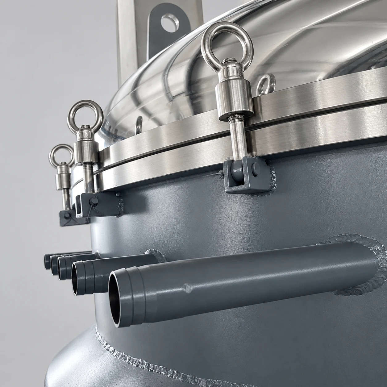
The lid joint and external housing features illustrate access and maintenance considerations. They are not an internal media diagram and do not establish the filter’s effective area, design pressure, or suitability for combustible service.
Diagnose an existing collector before changing its area
A rising pressure drop can indicate a deposit or cleaning problem, but it can also coincide with a changed gas flow or material duty. Verify the measured flow, differential-pressure instrument, cleaning supply and sequence, hopper discharge, and media condition. Compare the current process with the original design assumptions. Recalculate the ratio using observed conditions, while recognizing that the calculation does not identify every failure mechanism.
A low pressure drop is not automatically proof of good performance. A damaged element or bypass path can reduce resistance while worsening carryover. Include outlet observations and relevant emission measurements in the assessment. Review industrial filter sizing for the distinction between a housing envelope and its active filtering duty, while keeping liquid-filtration relationships separate from this gas-filtration calculation.
Combustible powder requires a separate hazard review. The HSE dust-explosion guidance addresses dust control and related protective considerations in food processing. Increasing filter area does not by itself prevent ignition, control explosion pressure, or isolate connected equipment.
Ask for a transparent supplier calculation
Provide the process material, representative sample information, actual airflow cases, gas conditions, collection objective, operating schedule, cleaning constraints, and required maintenance arrangement. Request the proposed gross and active areas, the selected ratio with its application justification, expected pressure-drop envelope, element replacement access, and commissioning checks. Clarify any performance statement and its test conditions before comparing prices.
YIYI’s dust collector product can start a discussion about the exterior vessel and connections. Confirm the offered media configuration and duty independently. The powder storage RFQ guide helps define the upstream material-handling conditions that should accompany the enquiry. A useful quotation ties the filter area to a documented operating case rather than relying on a model name or a housing photograph.
Educational video: industrial fabric filtration
NPTEL IIT Guwahati’s lecture explains separation using industrial fabric filters. It supports understanding the filtering mechanism and design context. The lecture is educational material and does not specify a filter ratio for an individual YIYI product or replace application testing.

Watch Lec 26: Separation by Industrial Fabric (Bag) Filters by NPTEL IIT Guwahati
Frequently asked questions
What units should air-to-cloth ratio use?
Use actual volumetric flow divided by active area with a consistent time basis. Cubic metres per minute divided by square metres gives metres per minute. State whether the flow is actual or standardized and whether area is gross or active.
Can I calculate filter area from the collector’s outside dimensions?
No. Outside housing dimensions do not establish the installed media geometry, element count, or usable area. Obtain the selected configuration’s drawings and the supplier’s area calculation, particularly for pleated or nonfabric elements.
Does adding more filter area guarantee better operation?
It changes the calculated loading at the same flow, but performance also depends on material, media, cleaning, distribution, discharge, and system conditions. Diagnose the actual problem and verify the revised design rather than relying on area alone.


