

Industrial filter tank sizing starts with the required filtrate quality, peak flow, liquid properties, solids load, available pressure, and operating cycle. Vessel volume alone does not determine filtration capacity. A granular-media vessel is normally evaluated through bed area, media depth, and backwash conditions; an element housing is evaluated through effective filter area, element resistance, dirt capacity, and service access. Specify the filtration mechanism before comparing sizes. This guide explains a sizing workflow for purchasers of industrial liquid filtration equipment, with a particular distinction between media tanks and reusable-element housings. Illustrations reference YIYI’s titanium-rod filter housing and do not imply that it is a sand filter or that any flow rating has been verified.
Identify what the filter must remove
Begin with a representative feed sample and a measurable downstream requirement. Describe suspended solids, particle-size distribution, expected variability, and whether particles are hard, soft, fibrous, or deformable. Record the consequences of breakthrough: a blocked spray nozzle, damaged heat exchanger, unacceptable product appearance, and microbial control require different evidence and acceptance criteria.
Mechanical particulate filtration does not automatically remove dissolved salts or all microorganisms. If the process problem is dissolved contamination, choosing a larger particulate vessel may not solve it. The EPA water-purification guidance distinguishes filtration and membrane treatment mechanisms. Apply its principles carefully to industrial liquids; drinking-water examples are not a validation of chemical-process performance.
Define the measurement method for the outlet requirement. A statement such as “clear liquid” cannot support reliable comparison unless everyone understands how clarity is assessed. Give the supplier a target particle removal, turbidity measure, or another appropriate agreed criterion, together with the sample conditions. Preserve the distinction between a process requirement and a product claim.
Choose the filtration mechanism before the vessel size
Search results for industrial filter tanks frequently describe multimedia, carbon, and water-treatment vessels. These are not interchangeable with a metal housing containing porous elements. Granular beds may require backwash expansion space and distribution systems. Element housings require suitable seating, seals, effective area, and element access. A calculation for one design cannot be transferred to the other merely because both have cylindrical shells.
For an element system, ask whether operation is dead-end, crossflow, or another arrangement, and whether cleaning takes place in the housing or after element removal. Establish which liquid path is dirty and which is clean. The titanium-rod filter product page provides a relevant equipment starting point, but an exterior photograph does not establish element count, filtration efficiency, or allowable differential pressure.
Use the stainless-steel filter-tank overview for general vessel considerations. Then request the actual supplier’s sectional drawing and element specification. The sizing decision should use verified configuration data rather than treating a polished stainless shell as proof of any particular internal mechanism.
Establish normal, peak and worst-case conditions
Record the normal production flow, credible peak flow, startup condition, minimum temperature, maximum viscosity, and expected solids excursions. A filter selected at warm clean-water conditions can lose useful capacity when the real liquid becomes colder or more viscous. The feed specification should state ranges and combinations that actually occur, rather than unrelated maximum values that never coincide.
Clarify whether flow is continuous or batch-based. A batch may permit a longer filtration time but still require a peak circulation rate elsewhere in the process. For continuous operation, decide whether production may stop during cleaning or whether a parallel standby unit is necessary. The Irish EPA filtration manual discusses capacity and redundancy in treatment systems; the same planning question matters when industrial production depends on a filter being available.
Confirm the available upstream pressure and the downstream pressure requirement at the intended flow. Do not allocate all pump head to the filter. Pipework, valves, elevation, and downstream equipment also consume pressure. Reserve an agreed allowance for fouling without exceeding the housing, element, or process limits.
Use area and loading calculations with explicit assumptions
For a selected superficial velocity or flux J, a preliminary active area is A = Q / J. Use consistent units: Q in cubic metres per hour and J in metres per hour produce A in square metres. The relationship is dimensional bookkeeping, not a method for inventing J. Obtain the allowable loading from relevant test data or supplier evidence for the actual media, fluid, and required quality.
As a hypothetical arithmetic example, a duty of 12 cubic metres per hour and a validated design loading of 6 metres per hour would require 2 square metres of active area. Those numbers are not recommendations and are not a YIYI rating. If the validated loading changes because of viscosity or solids behavior, the required area changes. The vessel diameter cannot be inferred until the internal arrangement and usable area are known.
For a granular bed, the area may be the bed’s cross section. For an element housing, use the effective filter area defined for the element configuration rather than the vessel’s cross section. Pleated, porous, and depth-media areas are not necessarily comparable without performance information. The retention requirement must remain linked to this hydraulic assessment; request the actual rating definition and efficiency evidence with the area calculation.
Estimate captured solids and the cleaning interval
A preliminary captured-solids rate can be written as mass rate = flow × feed concentration × retained fraction. With flow in cubic metres per hour and concentration in kilograms per cubic metre, the result is kilograms per hour. The retained fraction depends on the actual particle distribution and demonstrated filtration efficiency; a nominal micron label alone does not supply it.
For example, a hypothetical 10 cubic metres per hour, 0.05 kilograms per cubic metre of suspended solids, and a measured retained fraction of 0.8 produce 0.4 kilograms per hour captured. If an independently validated usable holding capacity were 2 kilograms, simple division would suggest five hours. Real operation may reach a pressure or quality limit sooner, so this is a screening calculation rather than a promised service cycle.
Describe cake compressibility, sticky deposits, and changing feed conditions when providing samples. Dirt capacity measured with a standard test dust may not predict behavior with a biological slurry or viscous process liquid. Ask how the supplier’s capacity test relates to the actual feed. Use a pilot trial where uncertainty is material to production continuity.
Compare proposals with a decision table
The table below organizes inputs rather than assigning universal limits. Filtration loading, redundancy, and operating controls should follow application-specific evidence, including the EPA guidance linked above.
| Sizing input | Why it matters | Evidence to provide or request |
|---|---|---|
| Peak and normal flow | Sets required hydraulic capacity | Process flow range and expected duration |
| Viscosity and temperature | Changes resistance and available capacity | Fluid properties at credible operating cases |
| Particle distribution | Connects retention and loading | Representative sample and analytical method |
| Solids concentration | Influences cycle length | Average, peak and upset measurements |
| Effective filter area | Supports flux comparison | Element configuration and area definition |
| Available pressure | Limits clean and fouled operation | Pump/system assessment and downstream requirement |
| Cleaning and redundancy | Determines production availability | Service procedure, cycle data and standby strategy |
| Material compatibility | Protects equipment and product | Fluid and cleaning chemistry specification |
Distinguish housing pressure from differential pressure
The housing design pressure and the allowable pressure difference across a filter element are separate limits. A vessel may withstand its specified internal pressure while an element is overloaded by excessive differential pressure. Both conditions must be addressed in the supplier proposal and operating controls. Include temperature dependence and pressure transients where relevant.
Measure inlet and outlet pressure at defined locations and record flow with the readings. A rising pressure difference at constant flow can indicate increasing resistance, but the interpretation changes if viscosity or flow changes. For related measurement-boundary principles, see the shell-and-tube pressure-drop guide. Its flow geometry differs from a filter, so do not transfer its resistance model to filtration media.
Set the cleaning or changeout condition using the applicable element limit, quality requirement, and operating envelope. Avoid adopting a convenient generic threshold. A damaged seal or bypass can reduce measured differential pressure while worsening filtrate quality. Monitoring pressure and outlet quality together provides a stronger basis for action.
Check cleaning space and safe service access
Allow space for element removal, closures, lifting arrangements, drain connections, and service tools. Vessel diameter may be acceptable while the installation location prevents safe maintenance. Ask the supplier to show the required service envelope on the drawing. Record any access-dependent cleaning or inspection activities in the installation plan.
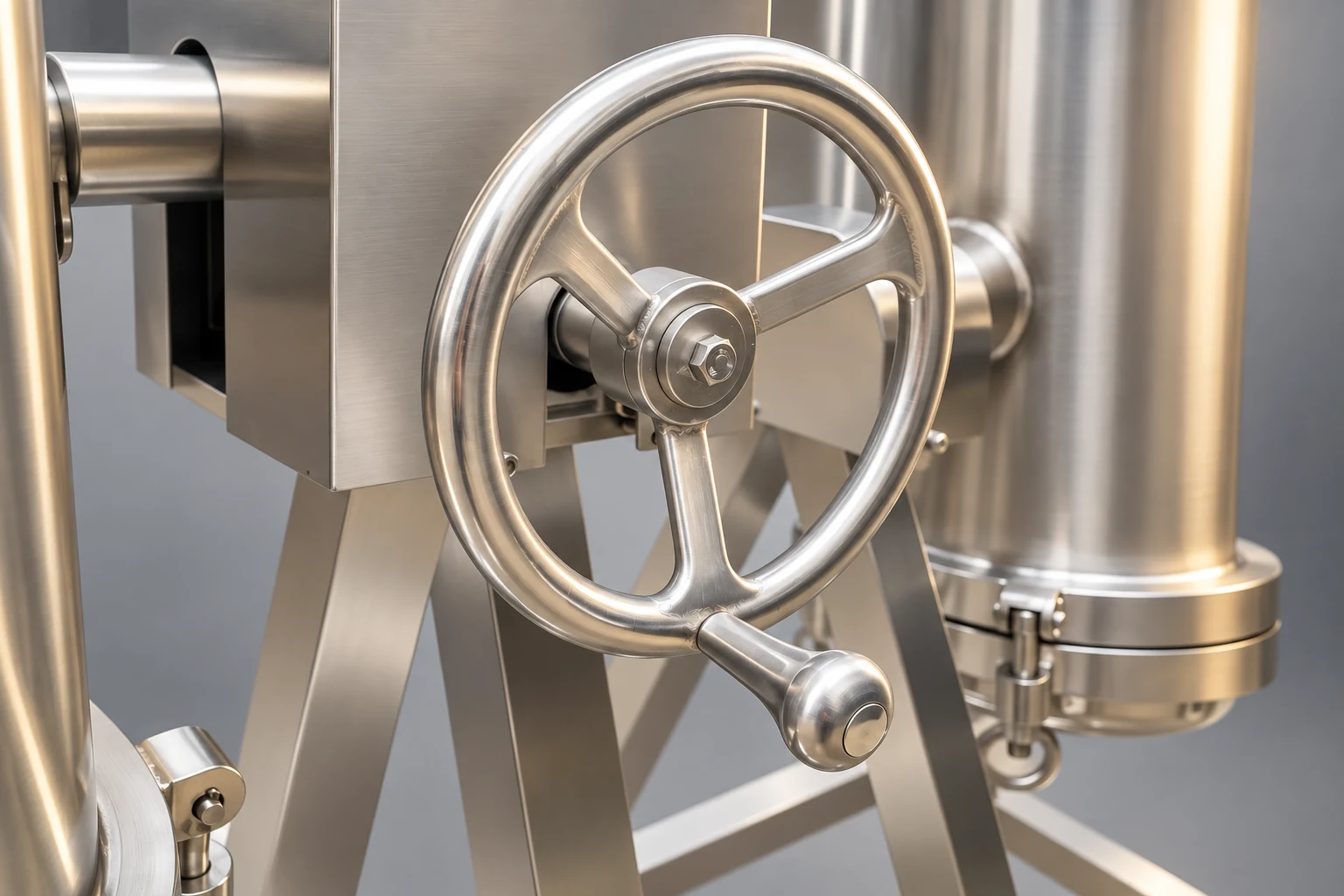
Cleaning arrangements should match the media and retained material. For reusable elements, request a validated procedure, compatibility statement, inspection criteria, and a method to verify performance after cleaning. Do not assume that backwashing instructions for a granular bed apply to porous titanium elements. The food-grade tank cleaning-validation guide explains broader acceptance planning; filter elements still require their own compatible procedure.
Further learning: filtration principles
NPTEL’s IIT Madras lecture introduces filtration in water and wastewater engineering. It supports understanding of filtration loading and retained solids, while the design conditions for chemical, food, or pharmaceutical liquids require their own assessment. The video does not provide a rated capacity for the illustrated YIYI housing.
Watch Lecture 13 Filtration by nptelhrd
Send a complete sizing enquiry
Provide the liquid identity, temperature and viscosity ranges, required outlet quality, normal and peak flow, solids data, available pressures, operating schedule, material requirements, cleaning constraints, and available service space. Request a proposal that states its assumptions and identifies missing information. Require clean and fouled hydraulic behavior, capacity evidence, and a recommended verification trial where necessary.
Compare proposals on the same duty and acceptance basis. The smallest vessel may be attractive initially but expensive if cleaning interruptions dominate production. A larger vessel may also be wasteful if it adds stagnant volume or difficult service access without improving the relevant active area. Ask for the engineering reason behind the proposed size and the evidence that the selected configuration satisfies the process requirement.
Frequently asked questions
Can I size a filter from tank litres alone?
No. Volume does not identify effective filter area, media resistance, retention efficiency, or dirt capacity. Establish the mechanism and operating conditions before comparing vessel volume.
Is clean-water flow a reliable process rating?
Only when the process duty matches the documented test conditions or a validated correction is available. Viscosity, solids, temperature, and required retention can change useful capacity substantially.
Does a bigger housing always give a longer cycle?
Not necessarily. Cycle length depends on usable media area and capacity, deposit behavior, quality limits, and allowable differential pressure. Request evidence for the actual element arrangement and feed.


