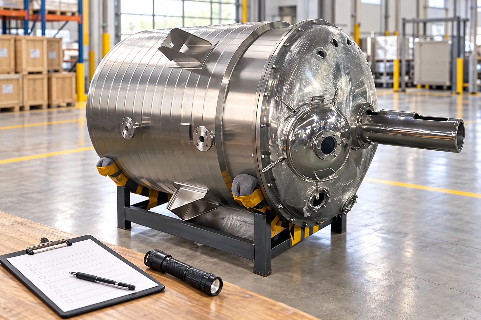
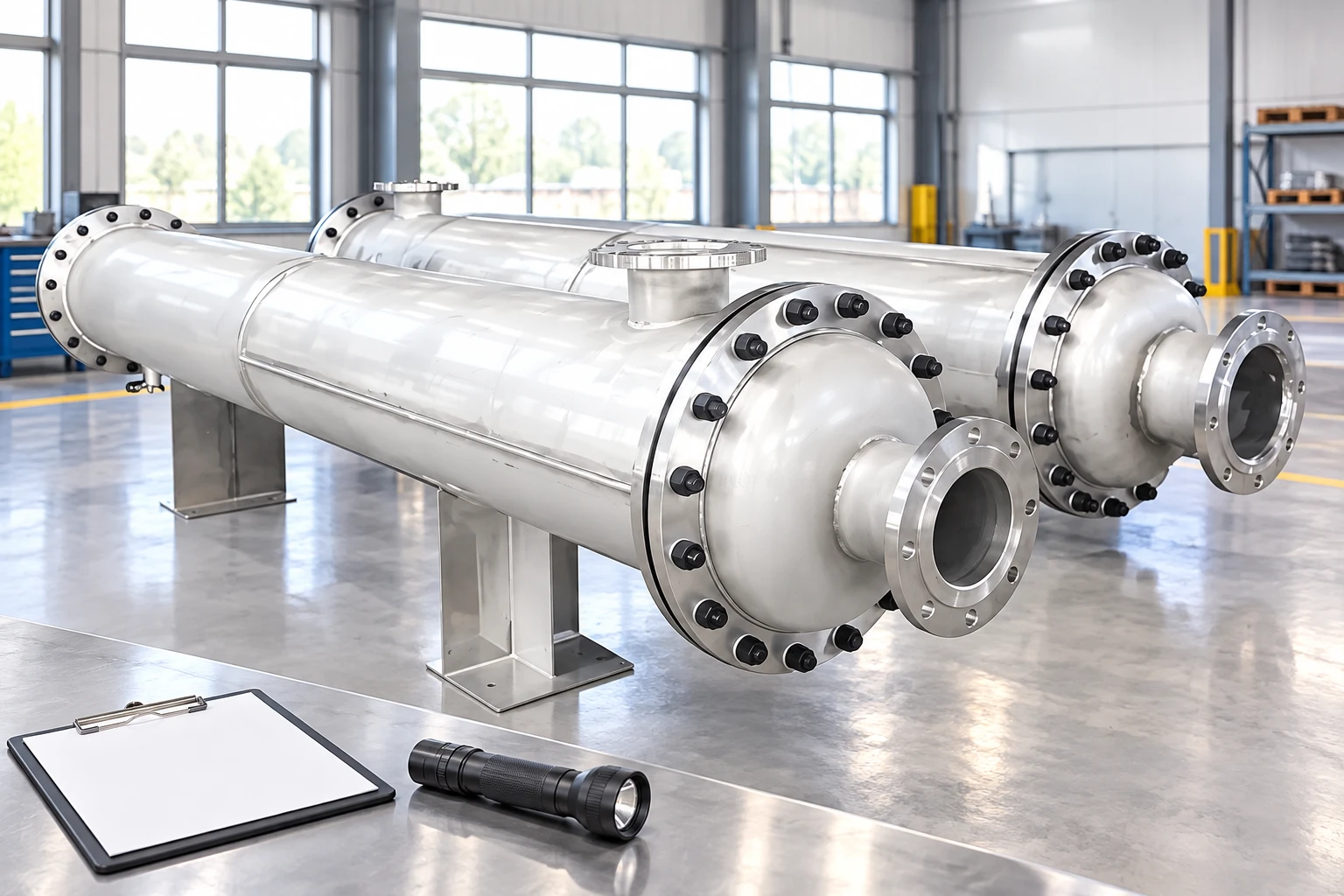
Dust collector system design begins at each dust source and works backward through hoods, ducts, collector, fan, discharge equipment and safety controls. Airflow alone is not a complete design basis: dust properties, capture behavior, transport velocity, pressure loss, fire and explosion hazards and maintenance access must be evaluated together. For industrial users, understanding the mechanism is useful only when it is connected to the real process, operating limits and maintenance plan. This guide explains the components, operating sequence, failure clues, selection questions and safe verification steps without assuming a particular manufacturer or inventing project ratings.
Contents
- Direct answer and operating purpose
- Main components and what each one does
- Step-by-step operating sequence
- How to read the application conditions
- What the device can and cannot tell you
- Common failure modes and warning signs
- Safe inspection and troubleshooting
- Selection and specification decisions
- Installation and commissioning checks
- Maintenance strategy
- Documentation and change control
- Questions to include in an RFQ or technical review
- Practical takeaway
Direct answer and operating purpose
Dust collector system design begins at each dust source and works backward through hoods, ducts, collector, fan, discharge equipment and safety controls. Airflow alone is not a complete design basis: dust properties, capture behavior, transport velocity, pressure loss, fire and explosion hazards and maintenance access must be evaluated together. The intended function should be written in plain language before equipment is selected. Separate normal operation from startup, shutdown, cleaning and abnormal conditions, because a device that works in one condition may be unreliable or unsafe in another.
Main components and what each one does
The main elements are capture hood, branch ducts, dampers, main duct, separator or filter collector, hopper, airlock, fan, exhaust and controls. Each element has a distinct job, but the assembly should be evaluated as one pressure, mechanical and control boundary. A component name does not prove its material, rating or compatibility. Use the manufacturer drawing and project data sheet to confirm construction.
Step-by-step operating sequence
Begin with the system in a known condition. Identify the energy source, the commanded action and the physical movement that produces the process result. Then follow feedback from the equipment to the operator or control system. For dust collector system design, the useful question is not merely whether it moves, but whether it reaches the required state under the worst credible operating condition. Confirm how travel begins, how it stops, how position or performance is verified, and what happens if power, air, flow or an instrument signal is lost.
| Review area | Evidence to request |
|---|---|
| Function | What must happen and how success is verified |
| Process | Fluid or material, operating range and upset cases |
| Mechanical | Materials, ratings, connections, loads and access |
| Controls | Energy source, command, feedback, alarms and fail state |
| Lifecycle | Inspection, cleaning, spares, records and acceptance test |
How to read the application conditions
Important application inputs include dust testing, source capture, airflow balance, duct transport, pressure-loss calculation, filter media, discharge, explosion protection and monitoring. Record minimum, normal, maximum and design or upset values with units. Identify which values are measured and which are estimates. The fluid or material description should include properties that influence corrosion, flow, heat transfer, contamination or wear. Environmental conditions can also change enclosure, coating, insulation and maintenance requirements.
What the device can and cannot tell you
Visible movement or a status signal proves only the condition it directly observes. It may not prove tight shutoff, accurate flow, clean internals, biological performance or adequate capture. Independent process measurements and inspection are often needed. Establish an acceptance method before commissioning so operators do not treat a convenient indication as evidence of a different result.
Common failure modes and warning signs
Relevant hazards and failure mechanisms include combustible dust, fire propagation, dust exposure, static, blocked ducts, rotating equipment and confined entry. Warning signs may appear as slower response, higher torque or pressure drop, leakage, unusual noise, temperature change, unstable readings, contamination, dust escape or declining process duty. One symptom can have several causes. Compare it with a clean commissioning baseline and inspect systematically instead of replacing parts by guesswork.
Safe inspection and troubleshooting
Put the equipment in a verified safe state before touching, opening or removing any component. Identify every energy source, isolate it, release or restrain stored energy, and verify the condition using the site procedure. Inspection should progress from external and non-invasive checks to internal work only when justified. Record the as-found condition before cleaning or adjustment, because that evidence often reveals the root cause.
Selection and specification decisions
A useful specification states the required result, operating envelope, materials, interfaces, safeguards, documentation and acceptance evidence. Avoid selecting from one catalog headline. Compare proposals against the same data sheet and require suppliers to list deviations. Check whether ratings apply to the complete assembly, including seals, accessories and controls, rather than only the body or one component.
Installation and commissioning checks
Before installation, review orientation, support, access, lifting, upstream and downstream conditions, drainage, utilities and connection loads. Confirm that identification and flow direction match the approved drawing. During commissioning, verify calibration, movement, interlocks and safeguards at controlled conditions. Record the initial response and inspection findings for future trend comparison.
Maintenance strategy
Base maintenance on the service severity and observable condition rather than an arbitrary universal interval. Define what operators inspect routinely, what triggers planned intervention and which tasks require shutdown. Keep compatible seals, wear parts and special tools identified. Changes in fluid, cleaning chemicals, temperature or operating frequency should trigger a review because they can invalidate the original maintenance assumptions.
Documentation and change control
Keep the approved data sheet, drawings, manuals, material information, test records and spare-parts list with the equipment history. Record changes to settings, components, operating conditions and cleaning methods. A replacement that appears physically interchangeable may use a different material, rating or control behavior. Require technical review before substitutions and update the drawing or parts list after an approved change. Good records allow a future technician to compare the current condition with the original baseline, identify recurring symptoms and order the correct part without guessing. They also make periodic safety reviews and supplier discussions more efficient because the team can refer to evidence instead of memory.
Questions to include in an RFQ or technical review
Provide the process description, operating cases, required function, materials constraints, site conditions, controls, cleaning approach and documentation needs. Ask suppliers to explain the basis of selection, exclusions, expected wear items, inspection access, testing and spare parts. For dust collector system design, request a drawing or functional description that makes the operating sequence and interfaces clear.
Practical takeaway
Understanding dust collector system design helps engineering, operations and purchasing teams discuss the same equipment without relying on vague labels. Define the function first, verify the mechanism against the real service, protect people during inspection and retain objective commissioning records. Project standards, local law and the approved manufacturer documentation always take precedence over a general article.
Authoritative references
Use official safety or technical guidance together with the relevant standards or public technical source. Confirm the edition and jurisdiction specified by the project.
Educational video
The following educational video from SAFE TEAM supports the mechanism or safety discussion. It is supplementary and does not replace the site procedure.

Related YIYI resources
Review the related equipment page and the parent product category. Complementary reading includes the stainless steel gate valve guide, industrial valve selection guide, and mixing tank specification guide.
Frequently asked questions
What is the most important fact to know about dust collector system design?
Dust collector system design begins at each dust source and works backward through hoods, ducts, collector, fan, discharge equipment and safety controls. Airflow alone is not a complete design basis: dust properties, capture behavior, transport velocity, pressure loss, fire and explosion hazards and maintenance access must be evaluated together.
How should the equipment be verified?
Verify the actual assembly against the approved drawing and data sheet, then use a controlled commissioning test with defined acceptance evidence. Do not infer performance from appearance or a single component rating.
When is specialist review needed?
Use qualified engineering and safety review when the service involves pressure, hazardous materials, combustible dust, biological hazards, stored energy or a change outside the original design basis.