

A silo hopper angle should be selected from the bulk material’s wall friction and strength, the required flow pattern, outlet dimensions and feeder interface. There is no single cone angle that prevents bridging for every powder. First state how the angle is measured: from vertical or from horizontal. Then obtain representative material-flow evidence and review the complete hopper and discharge system. A photograph, angle of repose or successful trial with another material cannot establish reliable flow for your duty. This guide explains the decisions to resolve before specifying or changing a hopper.
Define the angle reference before comparing drawings
One drawing may state the hopper half-angle from the vertical centerline; another may measure the wall slope from horizontal. Those conventions describe the same slope with different numbers. For a straight wall, the two referenced angles are complementary. Always put the reference direction beside the value and include a simple identified section on the supplier drawing.
For example, a wall shown at 30 degrees from vertical is at 60 degrees from horizontal. This example converts conventions; it is not a recommended angle for a powder or a claim about the vessel pictured here. Review whether a quoted value is a wall half-angle or an included cone angle, since those are also different descriptions.
An ambiguous specification can survive several quotation rounds before appearing on a fabricated vessel. Ask the supplier to confirm the geometry on a drawing, including transition height, outlet dimensions and available installation headroom. Avoid informal instructions such as a steep cone, which different teams can interpret differently.
Start with the required flow pattern
In mass flow, material moves throughout the stored bulk during discharge. In funnel flow, a central channel moves while some surrounding material remains stationary until conditions change. Which pattern is acceptable depends on the application, including residence time, segregation, contamination and the need to empty consistently. A flow pattern should be a deliberate design choice.
The Particle Technology powder-flow resources provide educational demonstrations of silo discharge. The supporting powder flow and storage chapter explains the material-property basis of hopper selection. Use these to understand the concepts, then obtain a design review for the actual material and proposed wall surface.
Distinguish arching from ratholing. An arch can form a stable obstruction over an outlet; a rathole can leave a stable channel surrounded by stagnant bulk. Both reduce usable storage and disrupt production, but they involve different conditions and may need different design responses. Opening a valve farther or steepening a wall is not an evidence-based remedy by itself.
Collect representative flow-property information
State particle-size distribution, bulk-density range, moisture, temperature, storage time and any known change during handling. These inputs help define the testing conditions. Ask whether samples represent ordinary production, a problematic batch or an ideal laboratory material. A test on unusually dry, freshly produced powder may miss the condition responsible for repeated plant blockages.
Wall friction must be assessed against a relevant surface. The proposed alloy, finish, wear condition and contamination can affect behavior. An angle chosen using one wall material should not be silently transferred to a different liner or surface finish. Provide the intended wall specification and ask the specialist what test surfaces and conditions are needed.
Cohesive strength and consolidation behavior are important for materials that can form stable obstructions. Storage time and loading history may change the result. Request a report explaining sample condition, test method, assumptions and the design cases represented. The objective is to understand the operating envelope, not simply to receive one number labeled flowability.
Keep wall angle and outlet size in the same review
A suitable wall slope does not remove the need to size the outlet. A cohesive material can still arch across an opening that is too small. Conversely, enlarging an outlet does not guarantee the desired flow pattern if the walls and material interaction remain unsuitable. Review the geometry as a system.
| Input or decision | What to establish | Why it changes the hopper review |
|---|---|---|
| Angle convention | Half-angle from vertical or slope from horizontal | Prevents fabrication and quotation ambiguity |
| Required flow pattern | Acceptable residence time, segregation and emptying behavior | Determines the desired discharge regime |
| Wall friction | Relevant material sample and proposed contact surface | Supports selection of a suitable slope |
| Material strength | Moisture, consolidation and storage-time cases | Informs arching and outlet review |
| Outlet geometry | Actual opening dimensions and transition shape | Governs the discharge interface and blockage risk |
| Feeder withdrawal | How material is removed across the outlet | Can support or undermine the intended flow pattern |
This is a qualitative decision table, not a sizing chart. None of its rows gives a universal angle or outlet diameter. The designer should document the relationship between the material evidence, selected geometry and intended flow pattern so that later substitutions can be reviewed properly.
Do not use angle of repose as a hopper design rule
Angle of repose describes the surface of a pile under particular conditions. It is different from wall friction and does not independently determine a mass-flow hopper slope. Particle shape, preparation and measurement conditions can also affect a pile observation. A photograph of a poured sample may be useful background, but it is insufficient evidence for final hopper design.
Likewise, a nominal cone angle taken from another installation is not transferable without checking material behavior and wall conditions. A vessel that empties freely with dry granules may behave differently with a fine cohesive powder or a material that has absorbed moisture. Describe the observed duty and ask what evidence supports any proposed reuse.
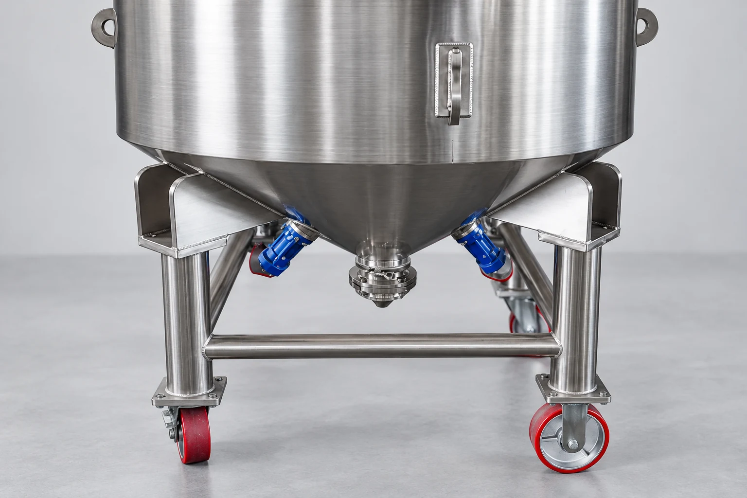
Separate simple geometry measurements from performance claims. The website’s compact stainless steel silo shows a real conical-bottom configuration. Its photographs do not establish an exact cone angle, mass-flow capability or resistance to bridging with your material. Request confirmed dimensions and application review rather than estimating from perspective.
Review the feeder and the full outlet interface
The hopper cannot be assessed independently of the device that removes material. Ask how the feeder draws across the available outlet, what the normal and peak rates are, and how the feed varies over its operating range. A downstream restriction or uneven withdrawal can affect the behavior of an otherwise carefully selected hopper.
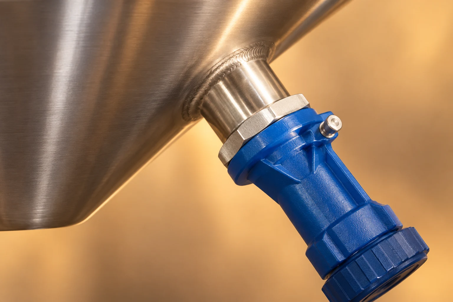
Identify valves, flexible connectors, short transitions and obstructions between the hopper and feeder. A large nominal outlet may connect to a much smaller effective flow area. Request a section drawing of the entire discharge path and include access for inspection, isolation and maintenance. Compare actual dimensions rather than equipment labels.
For a replacement feeder, check the existing hopper’s design basis before treating the change as a like-for-like repair. A different withdrawal pattern or capacity range may affect flow and usable inventory. Record the current performance symptoms and ask both equipment suppliers to review the interface together. The powder storage RFQ guide helps organize that broader operating data.
Diagnose the plant symptom before changing steelwork
Record when discharge stops: immediately after filling, after a long hold, at low inventory or only for certain batches. Note material temperature, moisture condition, feeder settings and upstream/downstream events. Distinguish a stable obstruction from an isolated receiver, closed valve or unavailable conveyor. Similar operator symptoms can have different causes.
Collect observations using safe, approved methods. Do not enter a vessel or disturb bridged material to diagnose flow. Grain and powders can present engulfment, mechanical and atmospheric hazards; refer to the site’s specialist assessment and procedures. The HSE confined-space guidance gives relevant safety context for restricted access.
Avoid prescribing vibrators, air injection or hammering as universal cures. A flow aid requires its own material, structural and safety review and may change segregation, compaction or dust behavior. Ask the responsible specialists to evaluate the proposed intervention, including how it is controlled and how success will be measured. An unverified aid should not disguise an unresolved geometry or feeder problem.
Compare proposals using an acceptance plan
Give all bidders a shared material description, sample plan, storage duration, inventory and feed-rate envelope. Include the proposed wall surface, cleaning method, permitted residual material, installation headroom and feeder interface. State which facts are known and which require tests. Request that each bidder show its assumptions and explain the selected geometry.
Agree how the design will be demonstrated. A representative trial should identify material condition, fill and hold history, withdrawal rates and the observations to record. Depending on the duty, relevant evidence may include discharge consistency, usable emptying, residual material and the absence of the identified failure condition. Set the criteria with the designer; do not invent universal tolerances.
Maintain the drawing and test report with the operating record. Changes in raw material, moisture, wall finish or feeder arrangement should trigger review of the original assumptions. For a terminology comparison before developing the specification, see silo versus grain bin. For maintenance context, use the steel silo cleaning guide. Send the material evidence and discharge duty with an inquiry so that recommendations can be assessed against measurable requirements.
Watch the discharge-pattern demonstration
The EngineerDo educational simulation below illustrates mass flow and funnel flow and is linked by the Particle Technology teaching resource. It helps visualize why the movement of the bulk matters. It does not supply a design angle for your material, prove performance of the photographed equipment or replace physical testing and engineering review.
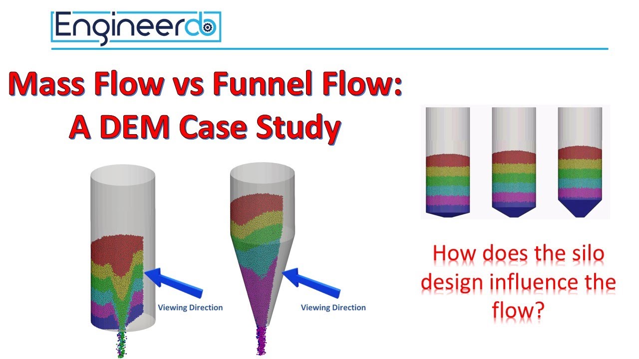
Watch Silo Design: Mass Flow vs Funnel Flow – DEM Case Study by EngineerDo
Frequently asked questions
Is a 60-degree hopper suitable for every powder?
No. First clarify the angle convention, then evaluate wall friction, material strength, outlet size and feeder behavior. A single slope cannot establish reliable discharge for all powders or operating conditions.
Is hopper angle the same as angle of repose?
No. A hopper angle describes vessel geometry, while angle of repose describes an observed pile surface under specified conditions. Angle of repose alone is insufficient for selecting a mass-flow hopper.
What evidence should support a hopper-angle recommendation?
Request representative material-flow data, the proposed wall surface, stated storage and consolidation cases, a dimensioned outlet and feeder drawing, the intended flow pattern and agreed acceptance evidence. Confirm which assumptions need further testing.


