

Sanitary heat exchanger CIP design should make every intended product-contact surface accessible to a validated cleaning cycle and allow cleaning liquids to leave through the approved drain path. Specify the circuit, active flow area, chemical compatibility, temperature, exposure time, and evidence of residue removal together. A polished exterior or a strong supply pump does not demonstrate effective cleaning inside all passes. This guide helps food, beverage, and bioprocess buyers translate a cleaning requirement into drawings, measurements, and acceptance records without inventing one universal recipe for different products and equipment.
Define the cleaning boundary and the actual soil
Begin with the product-contact circuit. Mark each heat-transfer passage, connecting return, valve, instrument connection, and shared pipe that belongs to the cleaning route. Identify separate utility circuits and explain whether they require their own cleaning program. A circuit that heats cleaning solution for another process has a different role from a product exchanger being cleaned internally.
Describe the soil from actual production: proteins, fats, sugars, mineral deposits, fermentation residues, or other relevant materials. Include the effects of heating, residence time, product changeover, and maximum dirty hold time. Fresh residues can behave differently from dried or heat-set deposits. Cleaning trials should represent the difficult intended condition instead of only an immediately rinsed unit.
The FDA cleaning-validation inspection guide explains the importance of a defined and documented cleaning process in its regulated context. Food plants should apply their own applicable requirements; pharmaceutical acceptance criteria are not automatically transferable to every beverage process.
Separate cleaning, sanitizing, and sterilizing objectives
Removing product residue, reducing microorganisms, and achieving a specified sterilization outcome are separate objectives. Identify which are required and how each will be verified. A clean visual appearance does not establish a microbial endpoint, and a heated sanitizing step does not prove that persistent soil has first been removed.
Specify the sequence and dependencies. If a sanitizing step requires a previously cleaned surface, make that condition explicit. If steam-in-place is required, assess the equipment, seals, drainage, air removal, and pressure-temperature envelope for that process. Do not assume that equipment described as suitable for CIP is automatically qualified for every sterilization cycle.
Ask the process owner to define acceptance limits and the test methods before quotation. A supplier needs to know whether the enquiry seeks cleanable construction, a developed cleaning recipe, documented validation support, or a complete automated system. Those are different deliverables and should not be bundled into a vague promise of hygienic design.
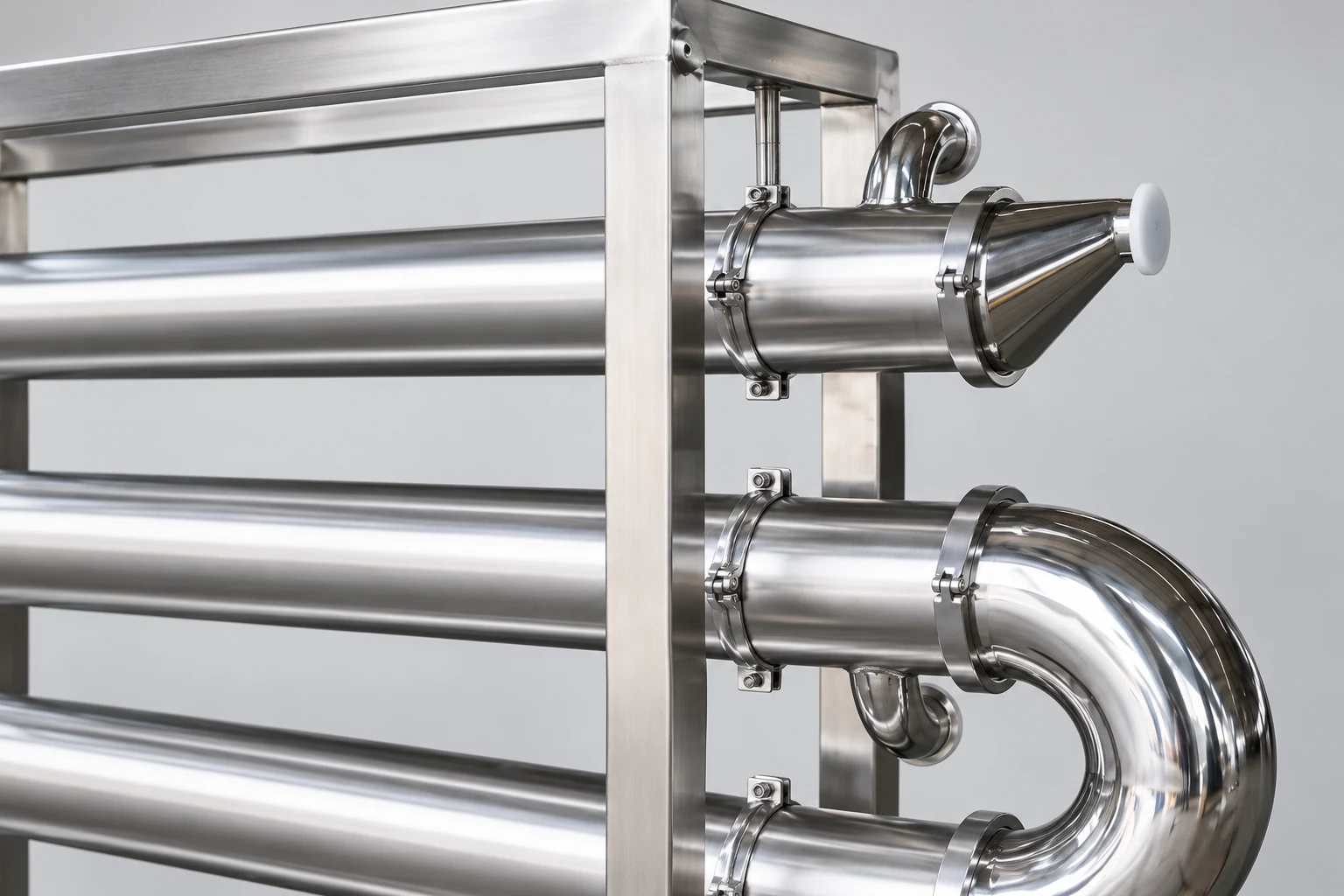
Calculate flow through the active product passages
For a simple uniform set of parallel circular tubes in one pass, a preliminary mean-velocity calculation is:
v = Q / A, with A = n × π × d² / 4.
Use Q in cubic metres per second, d as the actual internal diameter in metres, and n as the number of active parallel tubes in that pass. Velocity then has units of metres per second. Do not multiply by every tube in a multipass exchanger if only part of the bundle carries the flow in one pass. Pass partitions, blocked tubes, returns, and unequal distribution need attention.
For an illustrative circuit with ten active tubes of 20 mm internal diameter and 12 m³/h cleaning flow, Q is 0.003333 m³/s and A is approximately 0.003142 m². The estimated mean velocity is 1.06 m/s. These are hypothetical inputs, not a Kanger product specification and not a recommended cleaning limit. A measured supply flow does not prove that each parallel passage receives this average equally.
Cleaning effectiveness also depends on the actual liquid properties, surface condition, soil, chemistry, temperature, and time. Flow regime can be screened using Reynolds number when its assumptions apply. The separate tube-velocity guide explains the broader area calculation. Define the acceptable cleaning operating range through the approved process, rather than adopt the example velocity as a universal target.
Match the pump to the complete cleaning route
Calculate or verify pressure losses through the exchanger, valves, returns, supply and return piping, and other equipment in the cleaning circuit. A pump’s rated capacity at an unrelated operating point is not proof of delivered flow. Confirm the pump curve, fluid temperature, suction conditions, and actual route used during cleaning.
Check alternate paths and parallel branches. Cleaning liquid can prefer a lower-resistance route while another branch receives inadequate flow. Define valve positions and any sequencing needed to clean each branch. Include the return path in the assessment: a restrictive return can limit supply flow even when the pump appears adequately sized.
Instrument locations should support verification. Record flow, pressure, temperature, and chemistry at points that represent the conditions being claimed. A tank temperature alone may not show the temperature at the exchanger outlet during the hold period. A conductivity reading may help control a known recipe but does not by itself prove removal of every residue.
Make drainage a drawing-level requirement
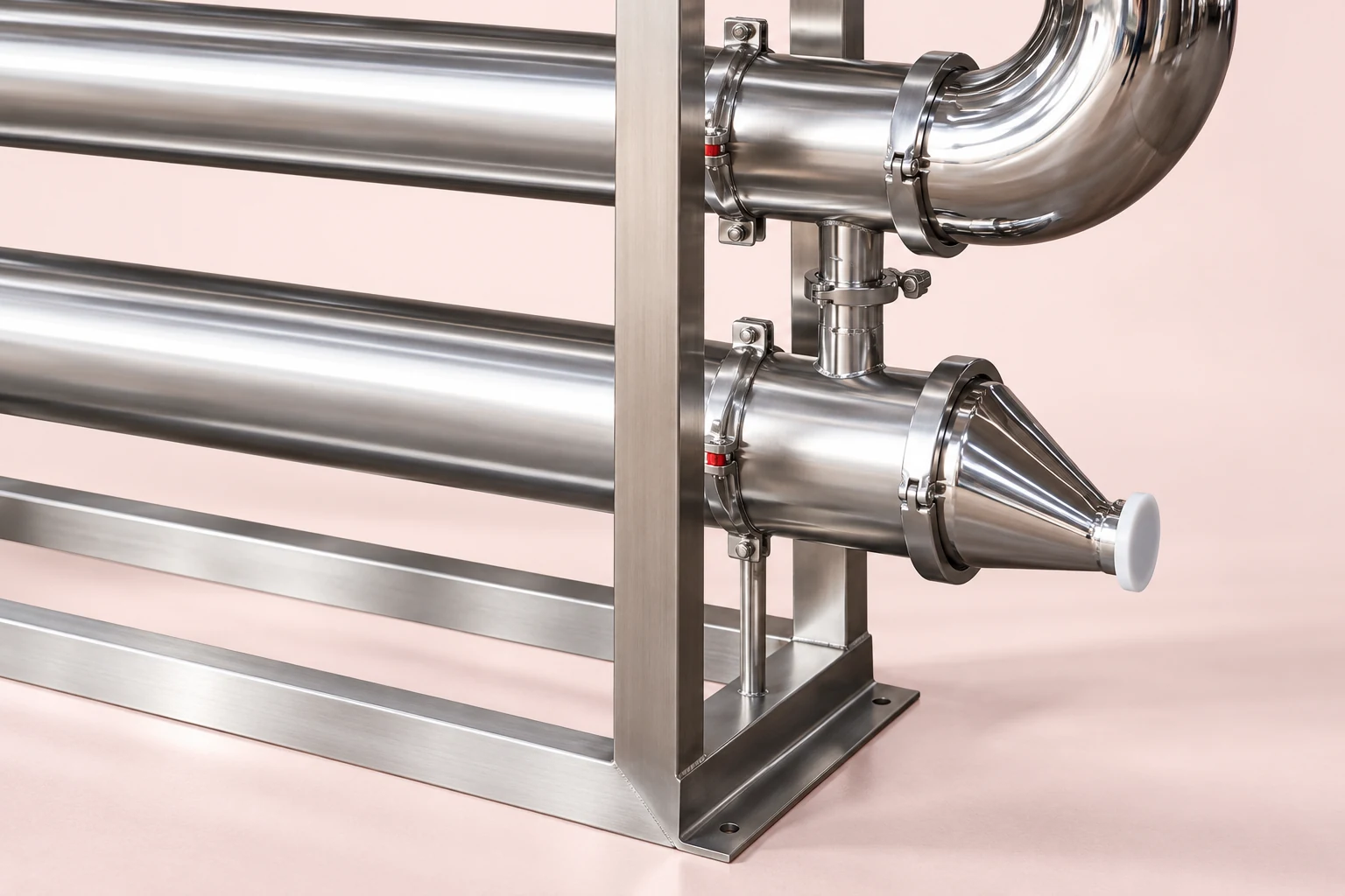
State the installation orientation and identify the intended low points, drain valves, vent paths, and residual-liquid concerns. External return bends and connections need inspection as part of the complete route. A model rendered level on a website does not establish the approved installation slope or the drainability of every internal surface.
Ask how air is displaced during filling and how liquid leaves during draining. Trapped gas can affect wetting and flow distribution. Retained liquid can dilute a subsequent step or remain after cleaning. Where a specific residual-volume requirement applies, define the test conditions and measurement method before accepting the equipment.
Keep cleaning access in view. A drain connection that can only be reached after removing surrounding pipework may frustrate routine verification. The Kanger sanitary multipass exchanger is a relevant equipment starting point. Request its supplied sectional and installation drawings to confirm the actual product path and drainage arrangement.
| Design question | Evidence to request | What a satisfactory review establishes |
|---|---|---|
| Product-contact boundary | Marked circuit and sectional drawing | Every intended surface belongs to a defined cleaning route |
| Active cleaning flow | Pass arrangement, internal dimensions, measured flow | Area calculations and operating measurements use the correct route |
| Drainage | Installation orientation, low-point map, test procedure | Residual-liquid behavior is checked under the intended arrangement |
| Chemistry compatibility | Wetted material and seal schedule, supplier limits | The proposed recipe fits the actual materials and temperature range |
| Cleaning endpoint | Sampling plan, methods, predefined limits | Acceptance follows evidence rather than appearance alone |
This table is a specification checklist. It intentionally provides no generic caustic concentration, time, or microbial limit; those values require a justified process basis and compatible equipment.
Review materials, seals, and connections with the recipe
List every wetted material and elastomer exposed to cleaning chemicals. Include maximum temperature, concentration, exposure time, and frequency for each cleaning step. Compatibility depends on the actual chemical mixture and service, not only a broad label such as stainless steel or food-grade rubber.
Cleaning can affect seals, deposits, and surface condition over time. Ask for the supplied seal identity, replacement guidance, and any restrictions on the recipe. If a gasket material is changed during maintenance, check whether the validated cleaning basis remains applicable. Preserve traceability to the approved component schedule.
Connection and joint details should support cleanability and inspection. Review crevices, instrument pockets, and any areas whose cleaning differs from the main passages. A good discussion distinguishes what can be demonstrated by drawings, what requires testing, and what remains the user’s process responsibility. Avoid treating polished photographs as evidence of internal finish or a particular certification.
Develop the cycle around measurable conditions
A cleaning cycle may include recovery, pre-rinse, chemical circulation, intermediate rinse, an additional cleaning step, final rinse, and sanitizing where required. The exact sequence depends on the product and validated process. Define the conditions required to start timing an exposure step rather than counting time from pump startup regardless of temperature or concentration.
Document the response when a critical condition falls outside its range. A low-flow event, chemical dosing fault, or inadequate temperature can invalidate part of the cycle. The response should explain whether the cycle pauses, repeats, fails, or requires investigation. Automated records are valuable only if the instruments and logic correspond to the process requirements.
Consider utility-to-product integrity as well as cleaning. The FDA heat-exchanger contamination guidance highlights separation concerns in relevant regulated operations. The required pressure relationship, integrity checks, and contamination response must be defined for the actual installation. Cleaning effectiveness does not replace an integrity assessment.
Validate difficult locations and preserve the evidence
Plan how residue removal will be measured at representative and difficult locations. Sampling access, recovery of the sampling method, analytical suitability, and the relation between rinse samples and inaccessible surfaces all need consideration. A negative result from an unrepresentative location cannot establish the whole exchanger’s condition.
Define worst-case production and cleaning conditions before the test. Include the intended product, dirty hold time, temperature exposure, and the least favorable approved cleaning settings. Document why the selected challenge represents routine service. A successful trial with an easier soil should not silently become proof for a harder product changeover.
Connect acceptance records to equipment identity, configuration, instruments, recipe version, and operator actions. Preserve deviations and their resolution. The commissioning checklist helps organize handover documents, while the bundle-maintenance guide addresses inspection access. Cleaning validation remains a distinct acceptance task with its own evidence.
Further learning: flow regime in a cleaning circuit
LearnChemE’s Reynolds-number example explains how velocity, diameter, density, and viscosity describe flow regime. It supports the flow discussion above; it does not prescribe a cleaning recipe or certify removal of a particular soil. Use measured cleaning-liquid properties and the actual passages when applying the principle.
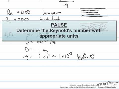
Watch Dimensionless Groups (Reynolds Number Example) by LearnChemE
Frequently asked questions
Is high cleaning flow sufficient by itself?
No. Effective cleaning depends on the route, distribution, soil, chemistry, temperature, time, and verified endpoint. A high pump rating does not demonstrate the delivered flow through every relevant passage.
Can a standard velocity be applied to every sanitary exchanger?
No. The required operating range should follow the approved cleaning process and equipment limits. Calculate the correct active area and verify the actual route rather than use a hypothetical example as a universal specification.
Does CIP suitability establish steam sterilization suitability?
No. Steam-in-place requires its own assessment of construction, seals, pressure-temperature conditions, drainage, air removal, and the required endpoint. Confirm those requirements explicitly before purchase.
What should the enquiry package contain?
Include the product and soil, cleaning boundary, intended recipe, wetted materials, operating limits, installation orientation, utility conditions, sampling needs, and acceptance criteria. Ask for drawings and testing responsibilities tied to the supplied equipment.


