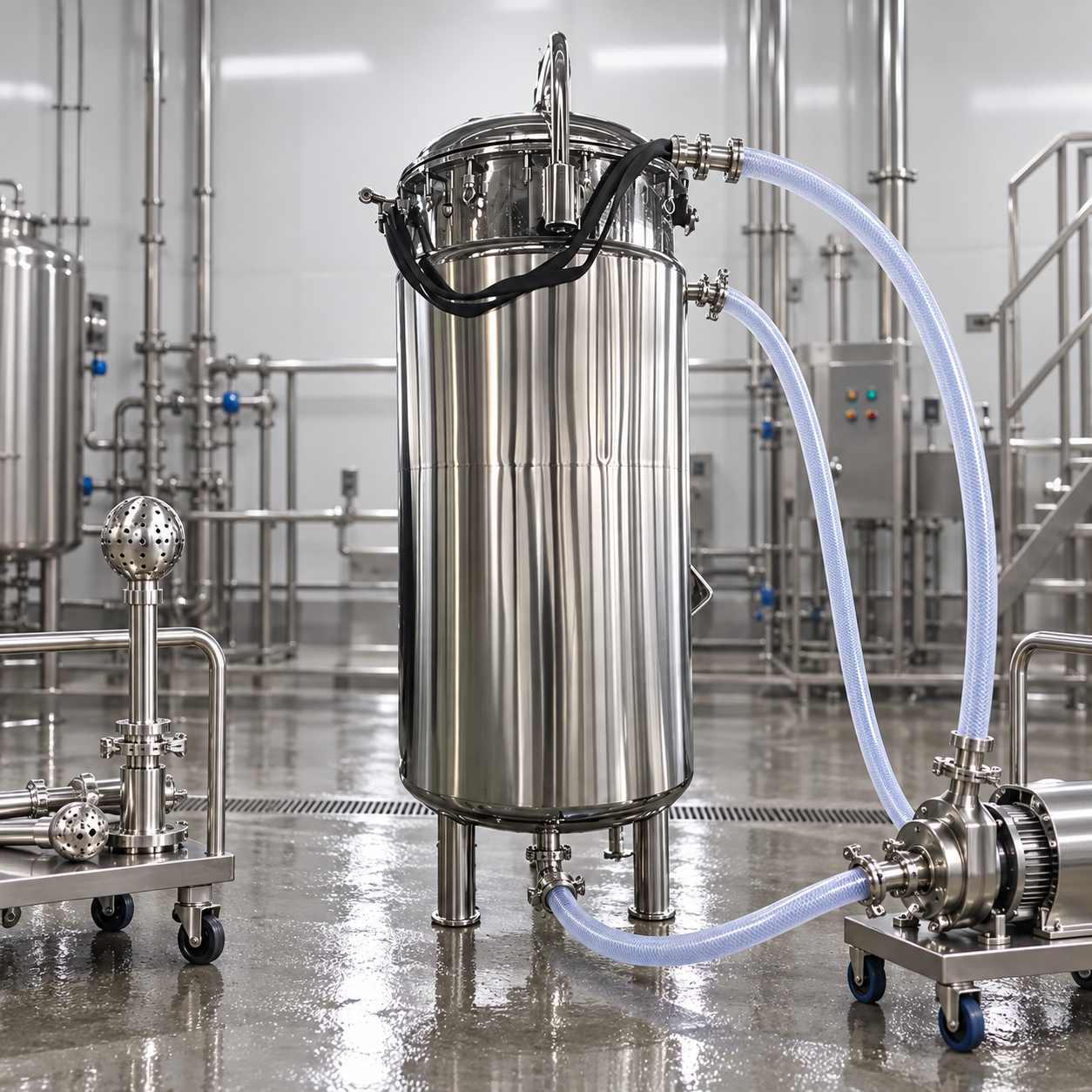
Storage tank leak testing should verify the specified boundary with a method capable of finding the defects that matter, without exposing an atmospheric vessel, lining, gasket, or worker to an unsuitable test condition. Shop acceptance and site acceptance often need different scopes: the shop can examine accessible fabrication seams under controlled conditions, while the site must confirm installation joints, piping interfaces, instruments, vents, supports, and final closures. A credible plan defines the test boundary, method, sensitivity, medium, pressure or vacuum limit, stabilization, inspection access, acceptance criteria, repair and retest rules, and traceable records.
Begin with the leak question, not the instrument
Ask what must be demonstrated. Is the concern gross leakage from a welded shell, seepage at a nozzle, product loss through a gasket, contamination into a hygienic tank, vapor escape from a volatile-liquid system, or long-term release from an installed tank? Different questions require different techniques. A water fill can reveal visible liquid leakage but may not show a small gas path. A soap-bubble test can localize accessible gas leakage but may be inappropriate on a dirty, hot, incompatible, or inaccessible surface. A helium mass-spectrometer method can be highly sensitive but requires suitable setup and acceptance criteria.
Write the required detectable leak level or practical acceptance basis before selecting equipment. “Leakproof” is not a measurable criterion. For many shop-fabricated atmospheric tanks, the contract may require no visible leakage under a defined hydrostatic head plus specified examination of welds. A high-integrity vacuum or pressure application may need a quantified gas-leak rate. The tank designer and owner must choose the basis; the test contractor should not substitute the most convenient instrument.
Respect the tank’s pressure and vacuum limits
Atmospheric storage tanks can be damaged by surprisingly small pressure or vacuum. Never pressurize a tank merely because compressed air is available. Confirm the maximum allowable internal and external pressure, temporary blank ratings, vent condition, and credible failure path. Use regulated supplies, relief protection, isolation, calibrated gauges with useful resolution, and a written sequence. Pneumatic energy can be dangerous because compressed gas stores energy; hydrostatic methods generally store less energy for the same pressure, but water load and drainage create other hazards.
Keep personnel away from temporary closures, manways, hoses, and fittings that could release suddenly. Do not stand in line with blanks. Verify bolting and gasket installation. If vacuum-box testing is used on accessible seams, control local vacuum and inspect the equipment seal. If pressure-decay testing is proposed, account for temperature stabilization and volume changes; a falling pressure is not automatically a leak, and a stable pressure does not prove every area was examined.
Compare practical shop test methods
| Method | Useful for | Main limitations |
|---|---|---|
| Hydrostatic fill | Visible liquid leakage, structural loading where specified | Heavy water load, drying and water-quality concerns |
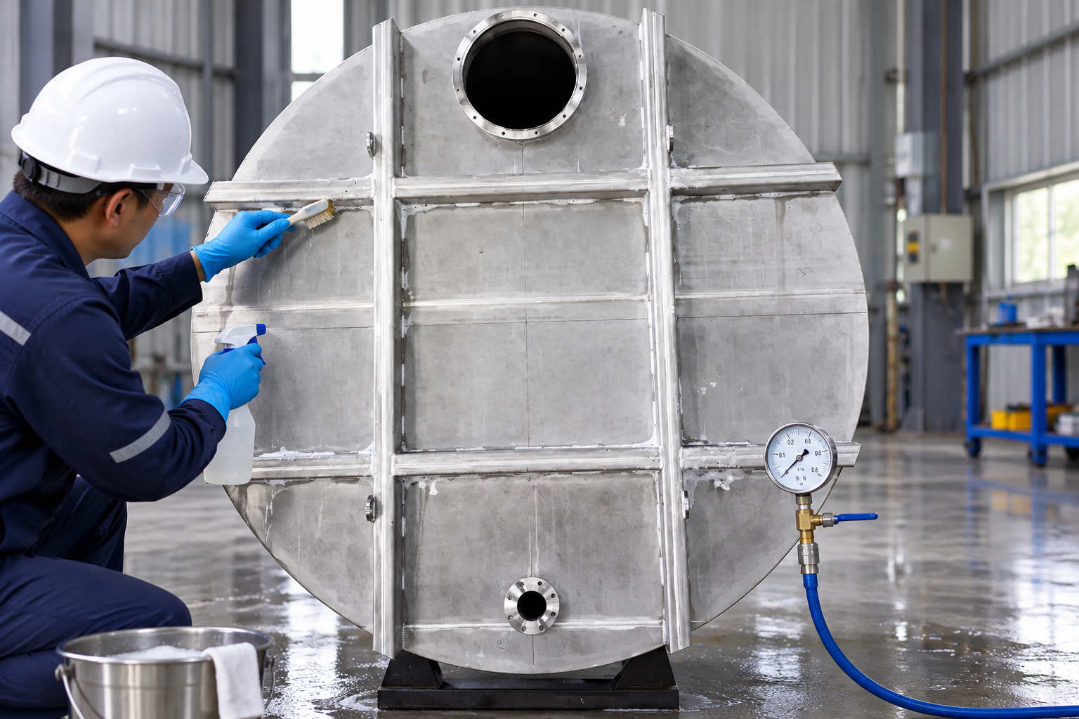
| Low-pressure bubble solution | Localizing accessible gas paths at welds and joints | Requires safe pressure control and compatible solution |
| Vacuum box | Accessible flat or gently curved weld seams | Coverage and seal depend on surface geometry |
| Pressure or vacuum decay | Overall closed-boundary screening | Temperature and volume can mask or mimic leakage |
| Tracer gas | Higher-sensitivity localization or quantification | Needs trained operators, controlled background and procedure |
| Dye penetrant examination | Surface-breaking discontinuities in clean nonporous material | It is an NDT method, not a complete tank tightness test |
No single method automatically covers every defect. The plan may combine weld examination, localized leak tests, and a final boundary test. Do not confuse radiography, ultrasonic examination, magnetic-particle testing, or penetrant testing with proof of overall tightness; each has a defined purpose and limitations. The approved inspection and test plan should show which method closes each quality requirement.
Prepare the boundary and surface
Use the latest drawing to mark included and excluded connections. List temporary blanks, installed valves, gaskets, instruments, relief devices, jackets, coils, and double-wall spaces. A jacket and the product chamber are separate boundaries and may have different limits. Clean external welds so bubbles, moisture, oil, or scale do not hide indications. Remove insulation or cladding from required inspection areas. Check that internal baffles or dip pipes do not create isolated pockets or trap test medium.
Before testing, complete required weld examinations and close documented repairs. Verify calibration, regulator function, relief protection, hose condition, and compatible test solution. Establish ambient and vessel temperature and allow stabilization when the method depends on pressure. Photograph dry baseline conditions. A pre-test briefing should identify the test controller, inspector, observers, exclusion zone, stop conditions, depressurization route, and emergency response.
Use controlled low-pressure bubble testing correctly
Where the tank design and approved procedure permit, low-pressure gas with a compatible bubble solution can identify leakage at accessible welds, nozzles, covers, and threaded or flanged joints. Raise pressure gradually through a regulator, never directly from an unrestricted plant-air source. Verify relief protection and remain below the established vessel limit. Apply solution systematically, allow the specified dwell, and distinguish growing bubble formations from foam introduced by brushing or spraying.
Mark and photograph confirmed indications without continuing to raise pressure. Depressurize safely before repair. Clean the solution afterward, especially on stainless or hygienic surfaces, and restore surface treatment if the repair requires grinding or welding. Repeat the affected area and any broader boundary required by the procedure. A “no bubbles seen” note is insufficient unless it identifies the pressure, dwell time, solution, locations, inspector, and conditions.
Plan site acceptance separately
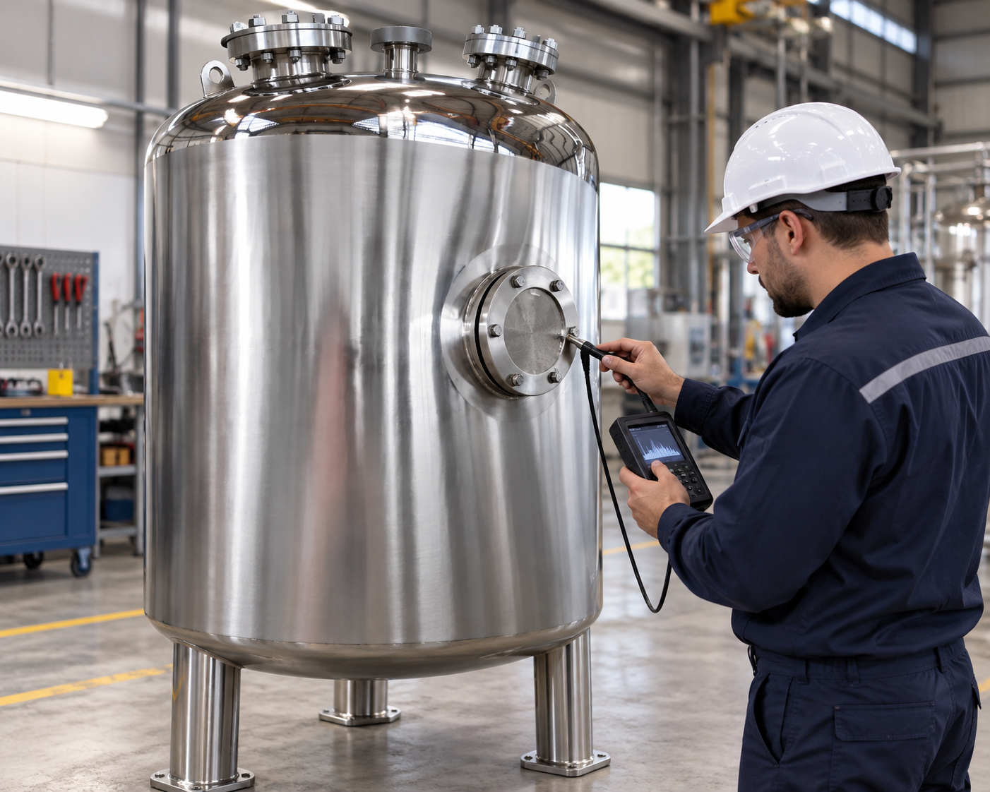
Shipping, lifting, foundation placement, field welding, piping connection, instrument installation, and insulation can change the boundary after a successful factory test. The site plan should identify what must be repeated and what new joints require testing. Check tank supports and piping loads before applying liquid head. Verify normal and emergency vents, overflows, drains, level devices, and leak-detection interfaces. For a double-wall tank, prove that the interstitial monitoring path is open and that the sensor can detect the intended condition.
Underground storage tank release detection is a specialized regulatory area. The U.S. Environmental Protection Agency explains multiple methods and applicability considerations in its release detection guidance for underground storage tanks. That guidance should not be copied blindly to an aboveground stainless process tank, but it illustrates an important principle: tank tightness testing and ongoing release detection are different controls. Passing an acceptance test does not replace operational monitoring.
Separate factory acceptance from ongoing monitoring
A factory or commissioning leak test provides evidence about the condition at one time under one set of conditions. It does not predict every future gasket failure, corrosion mechanism, impact, overpressure, or operator error. The owner needs an inspection and maintenance program based on product hazard, tank design, age, environment, legal requirements, and service history. Routine walkdowns, inventory reconciliation, interstitial monitoring, alarms, corrosion checks, or integrity inspections may be appropriate.
For chemical service, secondary containment and response planning remain necessary even when the tank passed. The chemical storage tank safety checklist covers operational safeguards, while the chemical storage tank design guide addresses material, venting, and containment inputs. Leak testing is one verification activity within that larger system.
Acceptance and repair rules
Define what constitutes a rejectable indication for each method. Visible liquid leakage, sustained bubble growth, a quantified tracer-gas rate above the specified limit, or decay outside the compensated criterion may trigger rejection, but the exact criteria must be approved before the test. Do not erase data by repairing first and documenting later. Create a nonconformance record tied to the location map, investigate the cause, approve the repair, complete required NDT, restore coatings or passivation, and repeat the required test scope.
Be cautious with sealants. Smearing an external product over a leaking weld may hide the symptom without correcting the fabrication defect and may be incompatible with the stored liquid. Any sealant, gasket change, or thread compound must be part of the approved materials system. Weld repairs require qualified procedures and personnel. The final record should show original failure, repair reference, retest conditions, and acceptance—not only the passing retest.
Documentation buyers should request
The turnover pack should include the approved procedure, tank and drawing identification, boundary sketch, risk controls, instrument and calibration list, test medium, environmental conditions, staged readings, inspection map, photographs, indications, nonconformance and repair references, retest results, final depressurization or drainage, restoration checklist, and witness signatures. For tracer-gas or instrument-based methods, include equipment model, sensitivity check, background reading, calibration standard, and operator qualification where required.
Compare the record against the purchase order before release. Confirm that the tested configuration matches what will ship and that temporary components have been removed. For product-contact tanks, verify cleaning and preservation after testing. For equipment from the storage tank range, specify leak-test requirements for the actual ordered configuration; a catalog category cannot define method or acceptance criteria.
Educational video
This EPA-associated educational video introduces underground storage tank leak detection requirements. It is included to clarify the distinction between a one-time tightness test and ongoing release detection; it is not a shop-test procedure for the tanks pictured here.
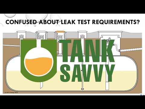
View the leak-testing educational video on YouTube.
Frequently asked questions
Is a hydrostatic test the same as a leak test?
A hydrostatic test can reveal leakage and may also verify structural behavior under liquid load, but it may not meet every required leak sensitivity. The project basis must define the purpose and acceptance.
Can shop air be connected directly to an atmospheric tank?
No. Atmospheric tanks may tolerate very little pressure. Any pneumatic test requires an engineered procedure, regulation, relief protection, calibrated measurement, and strict adherence to the tank limit.
Does a passing factory test eliminate site testing?
No. Installation creates new joints and potential damage. The commissioning plan should identify which boundaries and interfaces require site verification.