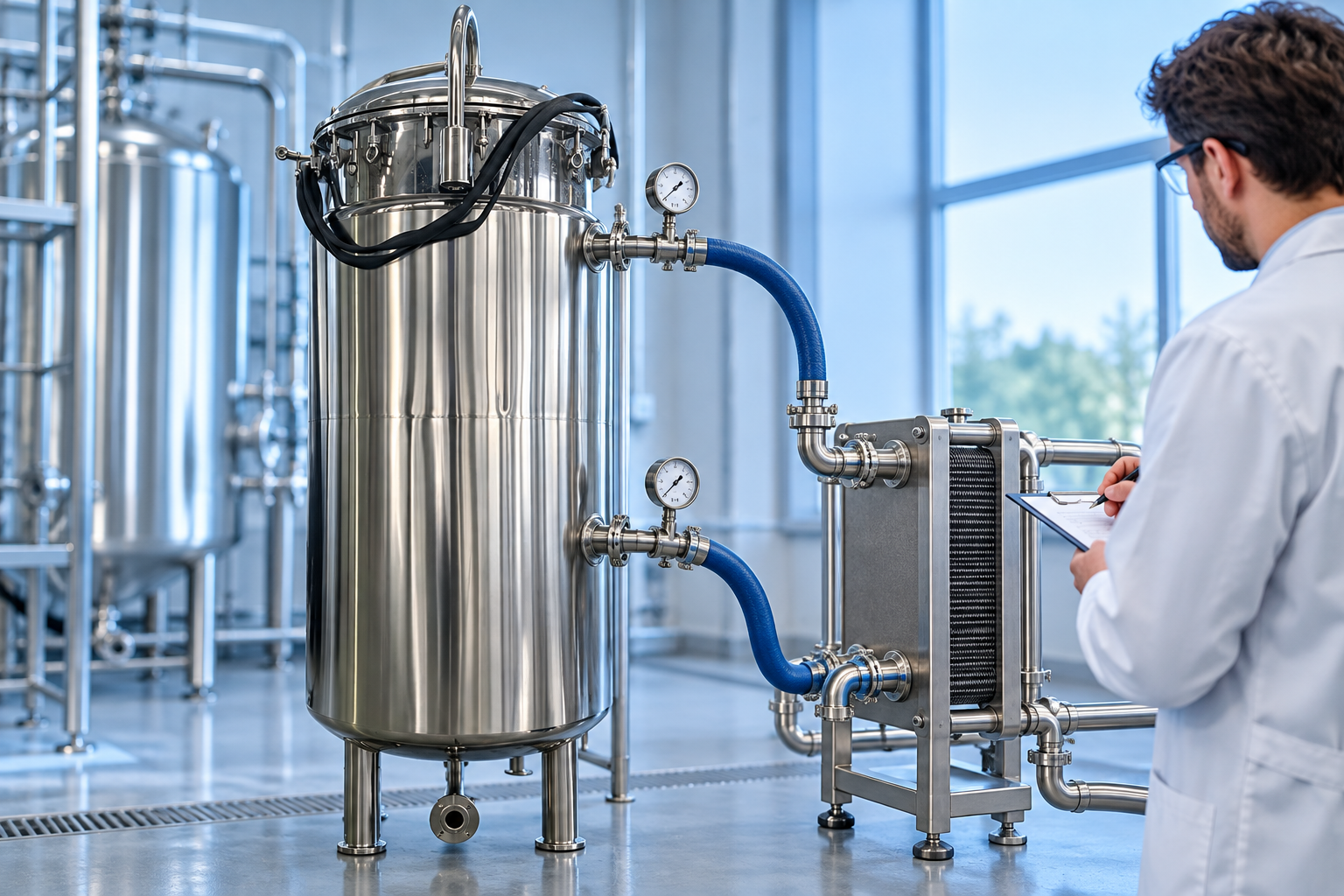
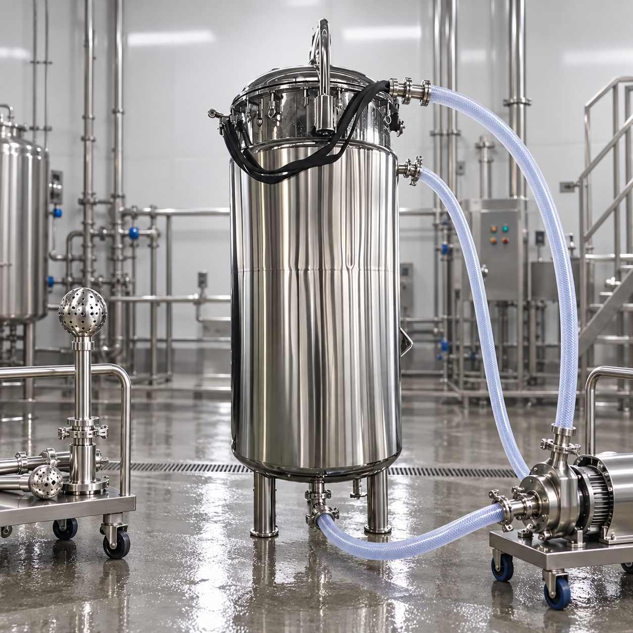
Storage tank overflow design should provide a predictable, visible, and safely routed path for liquid when normal level control fails or inflow exceeds the intended operating rate. The overflow is not a substitute for a vent, drain, high-level alarm, automatic shutdown, or operating discipline. A complete design starts with the maximum credible incoming flow, tank pressure and vacuum limits, liquid hazards, foam and vapor behavior, receiving location, backpressure, and maintenance access. Buyers should define these inputs before nozzle sizing and require a documented hydraulic basis, independent overfill safeguards where risk warrants them, and functional tests of the installed system.
Separate overflow, vent, drain, and relief duties
An overflow carries excess liquid away after the level reaches a fixed elevation. A vent admits or releases gas as the tank empties, fills, or changes temperature. A drain removes planned inventory from a low point. A pressure or vacuum relief device protects against specified abnormal pressure conditions. Combining these duties without analysis creates hidden failure modes. A liquid-filled overflow line can restrict air movement, while a vent routed to a liquid receiver can become sealed by product. Every connection should have a defined function on the piping and instrumentation diagram.
Atmospheric tanks are especially sensitive to small pressure and vacuum differences. OSHA’s flammable-liquids requirements state that atmospheric tanks within their scope must be adequately vented against pressure or vacuum from filling, emptying, and temperature changes. That rule is not an overflow-sizing formula, but it reinforces the boundary: the overflow route must not be treated as the only breathing path unless the responsible engineer has evaluated every operating state.
Define the maximum credible inflow
List every source that can feed the tank: transfer pump, gravity line, recirculation return, cleaning supply, condensate return, manual hose, and connected vessels. Consider simultaneous flows if valves or controls allow them. Use actual pump curves, maximum upstream head, valve failure positions, and credible control failures rather than the normal operating rate alone. If a positive-displacement pump can continue against restriction, its relief and shutdown arrangement belongs in the scenario review.
State the allowable liquid rise above the overflow invert and the available freeboard before another opening, roof feature, or vent becomes wetted. The designer can then calculate line capacity using the selected geometry, slope, roughness, fittings, entrance and exit losses, downstream level, and required margin. A nozzle nominally equal to the fill connection is not automatically adequate because elbows, long runs, elevation changes, or a partially submerged discharge can reduce capacity.
Place the overflow nozzle deliberately
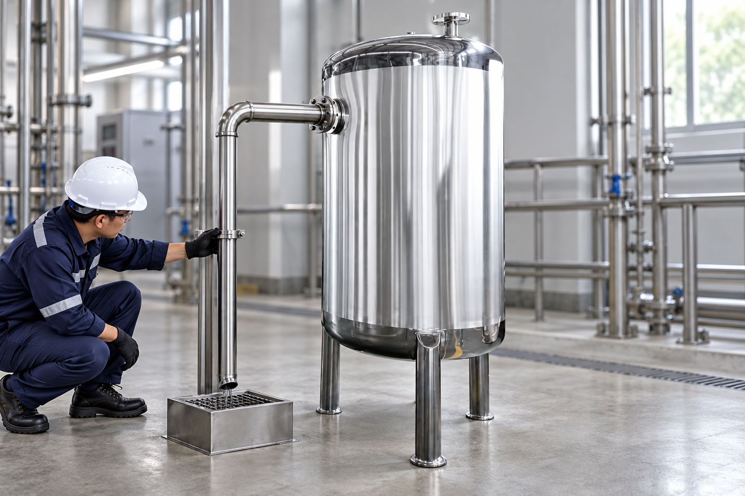
The nozzle elevation should correspond to the documented maximum operating limit, leaving enough freeboard for wave action, foam, thermal expansion, instrument response, and shutdown delay. Locate it where liquid can enter without being blocked by an internal baffle, spray ball, dip pipe, or floating material. A side nozzle may provide an obvious elevation, while an internal standpipe can offer flexibility but creates cleaning and inspection questions. The correct arrangement depends on product and tank geometry.
Avoid small screens, check valves, or normally closed isolation valves in the overflow path unless a risk review justifies them and controls their position. Screens can foul; check valves can stick; an unnoticed closed valve defeats the safeguard. If isolation is required for maintenance, use a controlled arrangement with position indication, lock or car-seal management, and an alternative protection state. The line should be inspectable and drainable rather than hiding a permanent liquid trap.
Route discharge to a safe receiving point
Do not allow overflow to fall beside the tank, onto access stairs, electrical equipment, hot surfaces, traffic routes, or soil. The receiving point must be compatible with the liquid and large enough for the credible event until inflow stops. Depending on service, it may be a closed recovery vessel, process drain, contained sump, return tank, or dedicated secondary-containment area. Evaluate vapor release, splashing, static electricity, worker exposure, incompatible mixtures, environmental rules, and how operators will recognize the event.
The discharge should remain visible or monitored without creating exposure. Where a closed receiver is necessary, calculate its backpressure and provide appropriate venting. Keep the outlet above the maximum receiver level or otherwise account for submergence. Provide an air break only where product hazard and contamination control permit it. If freeze protection, heat tracing, or flushing is needed, specify those features without obstructing the primary flow path.
Use independent prevention before relying on overflow
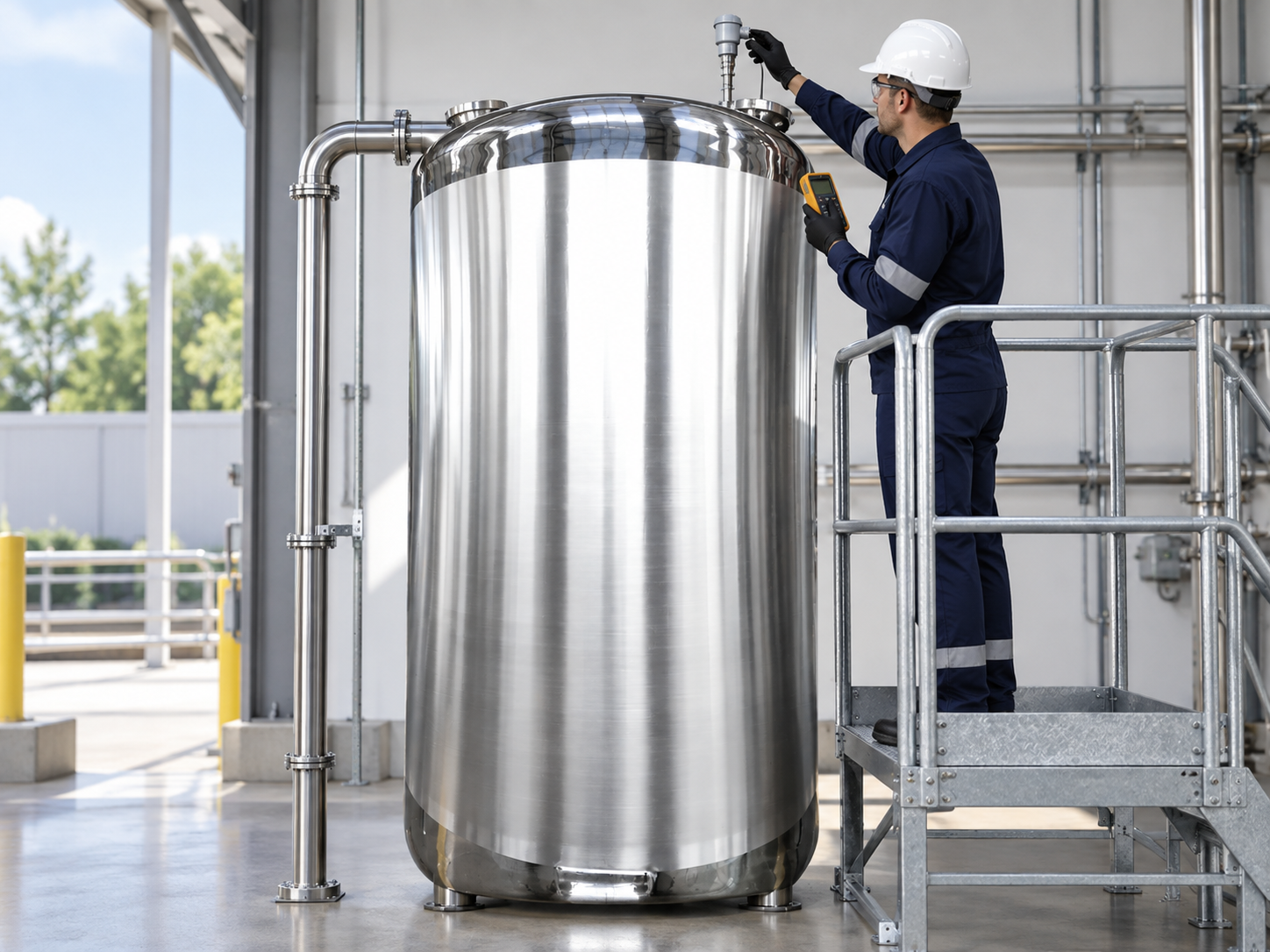
A high-level alarm gives operators time to respond; an independent high-high device can initiate automatic transfer shutdown where the hazard assessment requires it. Independence matters: two indications derived from the same transmitter, power supply, logic, or plugged process connection may share one failure. Define the proof-test method, interval basis, alarm setpoint, shutdown delay, valve travel time, pump coast-down, and total volume added before flow stops. The overflow remains a consequence-control path, not permission to accept unreliable level protection.
The U.S. Chemical Safety Board’s report discussing lessons from major fuel-storage events notes the move toward automatic overfill protection rather than sole reliance on manual interruption. Its regulatory report provides context for high-hazard bulk storage. A food, water, or low-hazard process tank may need a different protection layer, but every project should make the decision explicitly instead of assuming an overflow pipe solves the initiating failure.
Account for foam, solids, and product properties
Foaming liquids can reach the overflow before bulk liquid does, discharge two-phase flow, and contaminate vents or filters. Viscous products have higher friction losses and may drain slowly. Crystallizing, polymerizing, freezing, or solids-bearing liquids can plug a small nozzle or low-slope run. Hot liquid may flash or create thermal hazards at the receiver. Corrosive or hygienic services require compatible pipe, gaskets, supports, and cleaning arrangements throughout the entire route.
Use representative properties at the worst credible temperature. If a flush connection is needed, prevent it from becoming an uncontrolled fill source. Hygienic lines should avoid stagnant pockets and allow verified cleaning. A removable spool can aid inspection, but opening it must be controlled. For hazardous service, route vapors and liquid under the site’s process-safety and environmental basis. Never copy a water-tank overflow detail into solvent, acid, or hot-oil service without review.
Overflow design decision table
| Design input | Question to resolve | Evidence to request |
|---|---|---|
| Maximum credible inflow | Which sources can operate together or fail open? | Pump curves, valve states, scenario list |
| Available head and freeboard | How much level rise is acceptable before damage or carryover? | Tank section drawing and level setpoints |
| Liquid and vapor hazards | Can discharge foam, flash, freeze, corrode, or expose people? | Fluid data and hazard review |
| Downstream route | Is the receiver vented, compatible, and large enough? | Hydraulic calculation and destination drawing |
| Independent safeguards | What alarm or shutdown acts before overflow? | Cause-and-effect and proof-test procedure |
| Maintenance | How will blockage, valve position, and drainage be checked? | Inspection access and operating checklist |
Factory and site acceptance tests
At factory acceptance, confirm nozzle location, internal clearances, material, weld completion, and dimensional alignment. A controlled water test may demonstrate flow path and identify leaks, but the test rate and duration must be safe for the vessel and temporary receiver. Verify that the overflow does not siphon unexpectedly and that normal venting remains available. Record the test medium, rate, observed level, destination, and restoration.
At site, inspect supports, slope, low points, isolation status, receiver, venting, heat tracing, labels, and access. Function-test level alarms and shutdowns using an approved method; simulating a signal may test logic without proving the sensor. Confirm that the final fill rate and piping match the calculation. The storage tank leak-testing guide covers boundary verification, while the chemical storage safety checklist places overfill controls within the broader operating system.
RFQ wording for buyers
Provide the stored liquid, concentration, temperature range, density, viscosity, foaming or solids tendency, tank working volume, fill sources and maximum rates, vent basis, level limits, intended overflow destination, site elevation constraints, hazardous-area information, cleaning method, and applicable codes. Ask the supplier to identify assumptions and exclusions. Require a nozzle schedule, hydraulic basis, cause-and-effect interface, materials list, inspection plan, and test records.
The pictured 1,000 L alcohol receiving tank provides a relevant stainless vessel shape; it does not imply that the standard product includes the illustrated overflow or alarm configuration. Buyers should select and verify the arrangement for the ordered service. The broader storage tank range can be used to discuss vessel orientation and capacity before finalizing process connections.
Educational video
The U.S. Chemical Safety Board’s “Filling Blind” video explains how inadequate level information and overfill safeguards can contribute to a major storage incident. It is included for hazard awareness, not as a sizing method.
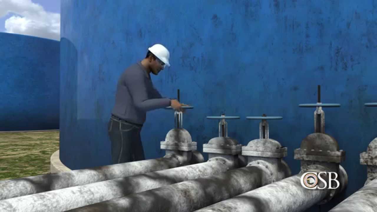
View “Filling Blind” on YouTube.
Frequently asked questions
Can the overflow pipe also be the tank vent?
Do not assume so. A liquid-filled or submerged overflow may block gas flow. Vent and overflow duties must be evaluated separately against the tank’s pressure and vacuum limits.
Should an overflow line have an isolation valve?
A normally closed or uncontrolled valve can defeat protection. If isolation is necessary, define position control, monitoring, maintenance state, and alternative protection through a formal risk review.
Does a high-level alarm eliminate the need for an overflow?
Not automatically. Alarm reliability, response time, shutdown volume, consequences, and applicable requirements determine the necessary layers. The project hazard assessment should define them.