A reactor sample must represent the process without exposing people or the environment to unnecessary risk. That becomes difficult when the vessel is pressurized, hot, oxygen-sensitive, toxic, corrosive, flammable, or prone to plugging. Opening a valve into a cup may be familiar, but familiarity does not make it representative or safe.
This guide explains reactor sampling system design for closed and hazardous processes. It covers sample-point location, dead volume, purge and return arrangements, cooling, pressure reduction, containment, and information needed for procurement. For the base vessel, see YIYI’s chemical reactor and complete reactor range.
Define what the sample must prove
Start with the decision the result supports. The sample may confirm reaction conversion, pH, color, moisture, particle size, catalyst concentration, contamination, endpoint, or release quality. Define the required phase, frequency, quantity, analysis time, temperature, and allowable exposure to air or moisture. A design that works for a low-viscosity aqueous liquid may fail for a crystallizing slurry or volatile solvent.
Representativeness is part of safety and quality. A small stagnant branch may contain old material and produce a false result, prompting an incorrect addition or longer reaction. Sampling plans should be developed with process knowledge and a documented quality basis. The U.S. FDA’s Process Analytical Technology guidance describes the value of timely process measurement, while NIST’s measurement traceability resources provide context for reliable measurements.
Locate the point in a representative zone
A sample nozzle should draw from a well-mixed region during the specified operating condition. Avoid a wall boundary layer, settled heel, gas pocket, feed plume, or direct outlet from an addition nozzle unless that is deliberately what must be measured. The proper elevation depends on minimum and maximum fill, agitator flow pattern, baffles, solids behavior, and phase distribution.
The process may not be homogeneous at all times. Define whether agitation must run before and during sampling, and at what speed. If the sample is taken after stopping the agitator, record the allowed delay because solids can settle and phases can separate quickly. For challenging duties, pilot testing or computational analysis may help, but a simple comparison of samples from different locations can also expose bias. The reactor agitator selection guide explains how impeller flow affects suspension and blending.
| Process condition | Primary design concern | Useful feature |
|---|---|---|
| Pressurized volatile liquid | Flashing, aerosol, operator exposure | Closed receiver, cooling and controlled pressure reduction |
| Toxic or potent material | Containment and decontamination | Closed-loop sampler, sealed bottle interface, purge/return |
| Slurry or crystallizing batch | Plugging and nonrepresentative solids | Short full-bore path, suitable valve, flush capability |
| Air- or moisture-sensitive product | Sample alteration and reactor contamination | Inert purge, sealed chamber, compatible septum or receiver |
| Hot corrosive liquid | Burn, vapor and material compatibility | Remote operation, sample cooler, corrosion-resistant wetted parts |
Control dead volume
Material trapped between the process and sample outlet can age, cool, react, crystallize, or separate. Before collecting the analytical sample, the system may require a defined purge volume. Sending that purge to an open drain wastes product and can create exposure. A closed loop that returns purge material to the reactor, or a designed recovery receiver, often provides a safer and more economical solution.
Keep the branch short and self-draining where possible. Avoid unnecessary reducers, pockets, threaded connections, and narrow passages for solids-bearing service. The valve should be close to the vessel connection so the isolated volume is small. Where a long remote line is unavoidable, trace, insulate, heat, cool, or flush it according to the material behavior.
Select a sampling architecture
Direct valve and container
A direct sample valve may be adequate for benign, low-pressure, low-temperature liquid when exposure and flashing risks are low. Specify a valve that drains and cleans, a controlled opening action, splash protection, and a stable container location. Do not use this arrangement merely because it is inexpensive when the process can release harmful vapor or hot liquid.
Closed sample receiver
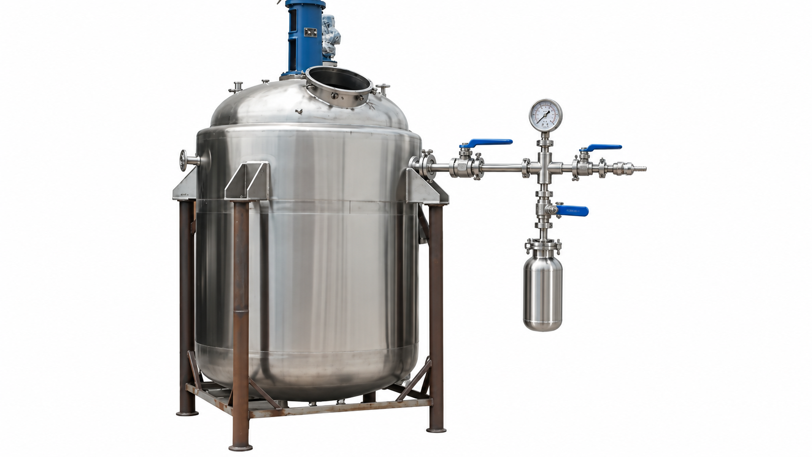
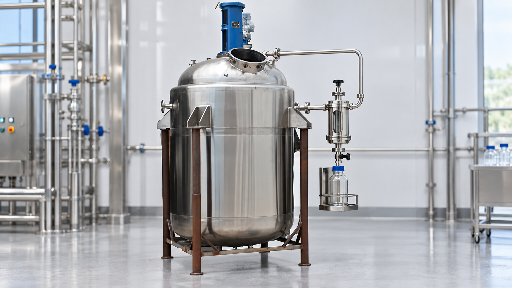
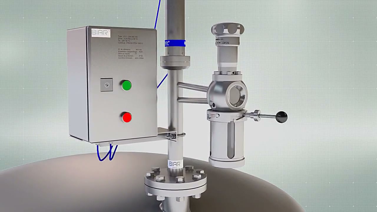
A closed receiver isolates a measured amount before transfer to a bottle or analyzer. Interlocked valve sequencing can prevent simultaneous open paths. The chamber must be rated for the maximum credible pressure and temperature, with a defined route for venting, draining, flushing, and relieving trapped pressure. A transparent component should be used only when its material and protection are suitable.
Fast loop or purge-and-return loop
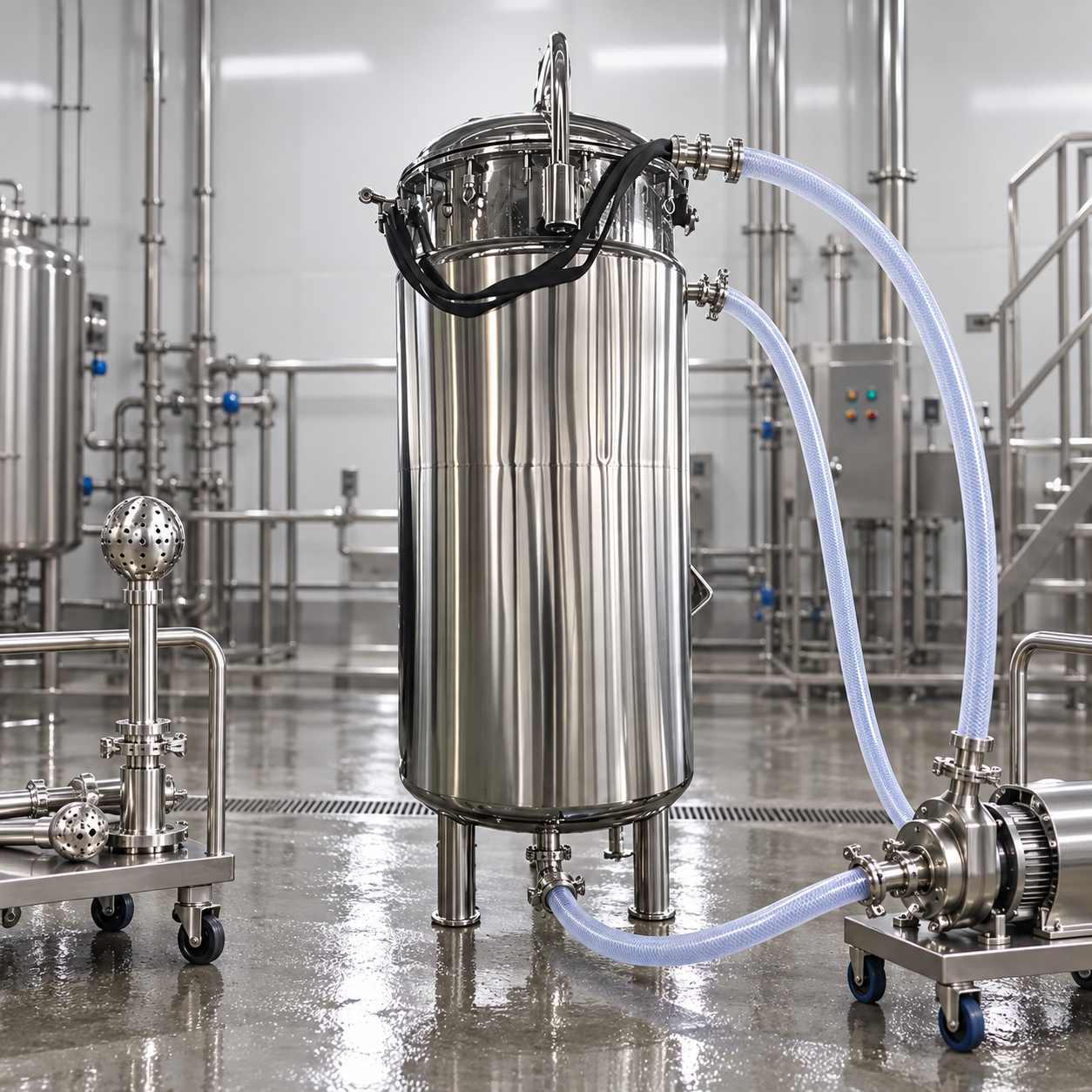
A circulating loop continuously or intermittently moves process fluid past the sample point and returns it to the reactor. It reduces lag and stale volume, and it can feed an online analyzer. The pump, restriction, and return nozzle must not create unintended reactor transfer or heating. Review failure modes such as blocked return, pump deadhead, reverse flow, seal leakage, and loss of agitation.
Dip tube or retractable probe
A dip tube can sample at a selected elevation but may plug, retain old material, or interfere with the agitator. A retractable probe permits service without opening the vessel only when it has reliable isolation and a safe retraction mechanism. Confirm insertion depth, mechanical support, vibration, cleaning, and the consequences of an accidental release.
Manage pressure, temperature, and flashing
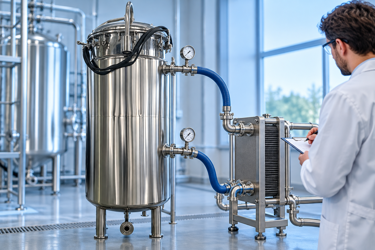
When process liquid crosses a valve, pressure can fall rapidly. A dissolved gas or volatile solvent may flash, cooling the sample and producing aerosol or two-phase flow. The liquid left in the bottle may no longer represent the reactor composition. Calculate or test the expected phase behavior and, where needed, cool the sample before pressure reduction in a rated exchanger or chamber.
Pressure reduction should be controlled and protected against blockage. Every trapped liquid section can experience thermal expansion. Every isolated chamber needs a defined safe depressurization path. The design pressure should reflect credible upstream pressure, including regulator failure or blocked outlet, rather than normal operating pressure alone. Relief must discharge to a safe system, not toward the sampler.
For exothermic or pressure-generating duties, integrate sampling into the overall control and relief review. Related design checks are discussed in reactor rupture disc versus safety valve and batch reactor sizing.
Contain hazardous material
Use closed transfer for toxic, carcinogenic, potent, odorous, pyrophoric, or environmentally harmful material. A sealed bottle adapter, split butterfly connection, glovebox interface, or double-contained receiver may be appropriate depending on exposure limits and quantity. Provide local exhaust only as part of a documented containment strategy; it does not replace source containment.
Materials of construction include all wetted metal, gasket, valve seat, tubing, window, and bottle interface. Confirm compatibility with process fluid and cleaning agents over the full temperature range. For oxygen- or moisture-sensitive chemistry, the sample path may need an inert purge and a sealed receiver. The nitrogen system requires controlled pressure and safe venting as described in reactor nitrogen purging.
Design for cleaning and cross-contamination control
A sampler can become the dirtiest part of an otherwise cleanable reactor. Define whether it is cleaned in place, flushed with solvent, steamed, sterilized, or removed. Confirm that cleaning media reaches the valve cavity, chamber, probe, return line, and bottle connection. Provide complete drainage and a way to verify the clean state.
For multiproduct service, establish the equipment boundary and residue limit. A small uncleaned sample leg can contaminate the next batch or produce a false first sample. Use the same risk-based principles described in reactor cleaning between products. Disposable tubing or containers can reduce cross-contamination only if their compatibility, integrity, and connection method are controlled.
Operating sequence and safeguards
- Verify readiness. Confirm the batch, sample point, receiver, container, personal protection, vent and waste routes.
- Establish mixing. Use the specified agitator speed and stabilization time so the sample has a defined basis.
- Refresh the path. Circulate or purge the validated volume to return or a closed receiver.
- Isolate the sample. Follow the valve sequence that prevents an open path from reactor to atmosphere.
- Condition it safely. Cool and depressurize in rated equipment when required.
- Fill and seal. Avoid headspace or air contact when the analytical method requires it.
- Restore and clean. Drain, flush, inert, and return valves to their defined normal position.
- Label and document. Record time, batch, location, process conditions, operator, and any deviation.
Useful interlocks can prevent opening the bottle valve before the process valve is closed, block sampling above a temperature limit, or alarm a blocked return. Position indication and a simple sequence diagram reduce mistakes. Automation should fail to a contained state and still allow safe depressurization.
OSHA’s hazardous-waste resources offer context for exposure and handling programs, but the employer must select controls using the actual chemical hazards and applicable regulations. Safety data sheets alone do not replace a process-specific review.
Information to give a sampler or reactor supplier
- Fluid composition, toxicity, flammability, corrosivity, solids, viscosity, vapor pressure, and tendency to crystallize.
- Reactor pressure, temperature, fill range, agitation state, sample frequency, volume, and required phase.
- Allowable operator exposure, emissions, air/moisture contact, and sample temperature.
- Preferred purge destination, return pressure, cooling utility, inert gas, cleaning method, and waste route.
- Materials, hazardous-area classification, valve sequence, instruments, interlocks, bottle type, and analytical interface.
YIYI can coordinate the vessel nozzle, dip tube, agitator clearance, access, instruments, and control interfaces with a chosen sampling package. The final system should be reviewed by the owner, sampler specialist, and process-safety team as one connected pressure system.
Frequently asked questions
Where should a reactor sample point be located?
Place it in a representative mixed zone across the required fill range, away from a feed plume, wall boundary, gas pocket, or settled heel. Confirm the location using process knowledge and representative-sample testing.
Why use a purge-and-return sample loop?
It refreshes stagnant volume and returns purge material to the process, reducing waste and exposure. It must still be designed for blocked flow, reverse flow, cleanability, and credible pressure.
Does a pressurized reactor sample always need cooling?
No, but cooling is often needed when pressure reduction would cause flashing, aerosol, burns, sample fractionation, or damage to the container or analyzer. Evaluate the actual phase behavior and sampling temperature.