

A dosing tank calibration drawdown test checks delivered chemical flow by measuring a known reduction in liquid volume over a measured time while the dosing system operates under representative conditions. The basic calculation is flow = volume change divided by elapsed time. A useful test also accounts for vessel calibration, suction arrangement, discharge pressure, air, temperature, and measurement uncertainty. It verifies the tested operating point; it does not establish accuracy across every pump setting or replace calibration of the complete treatment process. Use a compatible, closed or otherwise approved test arrangement and a documented chemical-handling procedure.
Define exactly what is being calibrated
Separate pump setting, delivered liquid flow, active chemical concentration, and final process dose. A pump may deliver the expected litres per hour while the stock solution has the wrong concentration. Conversely, a correct solution can be underfed because of air, a restriction, or an incorrect speed setting. The test must state which quantity it measures and what additional evidence is required.
The broader chemical dosing-tank integration guide explains the feed-loop arrangement. Drawdown testing focuses on a field measurement of actual liquid delivery. Record the complete route from the calibration vessel through the pump to the receiving process so a bypass, return line, or leak cannot silently invalidate the measured result.
Choose a compatible measurement arrangement
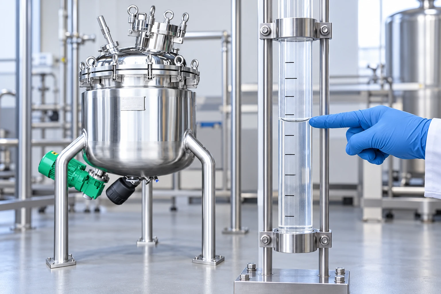
Use equipment rated and chemically compatible with the liquid, pressure conditions, temperature, and cleaning procedure. A calibration column is one possible arrangement, but it needs suitable isolation and a safe fill and drain method. Do not improvise an open graduated container for a hazardous, volatile, or reactive chemical. Consider exposure, spill containment, ventilation, and the consequences of a broken or emptied column.
The Pennsylvania Department of Environmental Protection’s chemical feed training workbook provides operator context for chemical feed systems and calibration. Apply its principles with the actual equipment instructions and site requirements. It is not evidence that a particular tank or pump has been approved for the chemical.
Verify the volume scale before trusting it
A tank level change is not automatically a known volume change. Use a verified calibration table for the actual vessel geometry and installed orientation. A narrow column may improve reading resolution, but meniscus interpretation, scale spacing, and liquid motion still matter. Foam can make a liquid boundary difficult to identify, and opaque or viscous material may need another measurement method.
A gravimetric alternative measures mass change over time. Converting mass flow to volumetric flow requires density at the relevant concentration and temperature. Do not assume water density for a concentrated chemical. Keep the original mass result and its measurement conditions. The NIST calibration resources and SI guidance support consistent, traceable measurement rather than an undocumented scale assumption.
Reproduce the real operating conditions
Test at the intended pump setting and a representative discharge pressure. A test discharging into an open container may give a different result from injection against process pressure. Check whether the calibration arrangement changes suction head or introduces an unusual restriction. The measured flow is only transferable to production when those differences are understood.
Prime the system by the approved method and confirm that the measurement section contains liquid rather than an unknown air volume. Record liquid temperature, stock concentration, pump speed or stroke setting, and valve positions. If the process uses intermittent dosing, define whether the test measures flow while running or the time-averaged delivery including off periods. Those values answer different questions.
| Test field | What to record | Why it matters |
|---|---|---|
| Liquid identity | Chemical, concentration, temperature, density basis | Properties affect volume conversion and pump behavior |
| Measurement vessel | Scale verification and usable reading range | Level reduction must represent a known volume |
| Pump setting | Speed, stroke or other active control | The result belongs to a particular operating point |
| Hydraulic condition | Suction arrangement and discharge pressure | A test arrangement can alter delivered flow |
| Timing | Start, stop, elapsed time and reading method | Timing error matters especially in short tests |
| Repeat result | Individual readings and spread | Inconsistency can reveal air or unstable operation |
| Acceptance | Permitted error and required operating range | A pass requires a pre-agreed criterion |
No universal acceptance tolerance is implied by this table. Define it from the process dose requirement and the actual measurement capability. A test cannot demonstrate a tighter tolerance than its uncertainty reasonably supports.
Perform and calculate a drawdown test
Stabilize the pump and process condition before taking the initial reading. Start timing consistently with the selected reference level, and stop at the defined final level. Choose a duration and volume change large enough to resolve the scale and timer adequately without emptying the suction source. Record both readings rather than only the calculated difference.
For a hypothetical example, a 0.75-litre reduction over 180 seconds gives Q = 0.75 × 3600 / 180 = 15 litres per hour. If the test is repeated at another setting or pressure, calculate and record that result separately. These values illustrate the unit conversion; they are not a recommended test duration or a pump performance claim.
Repeat at relevant operating points, especially the low and high ends of the intended range. Keep the raw values, note any unstable readings, and investigate material disagreement between repeats. Do not average away a run affected by an air pocket or a changing discharge pressure. Label the deviation and repeat after correcting the cause.
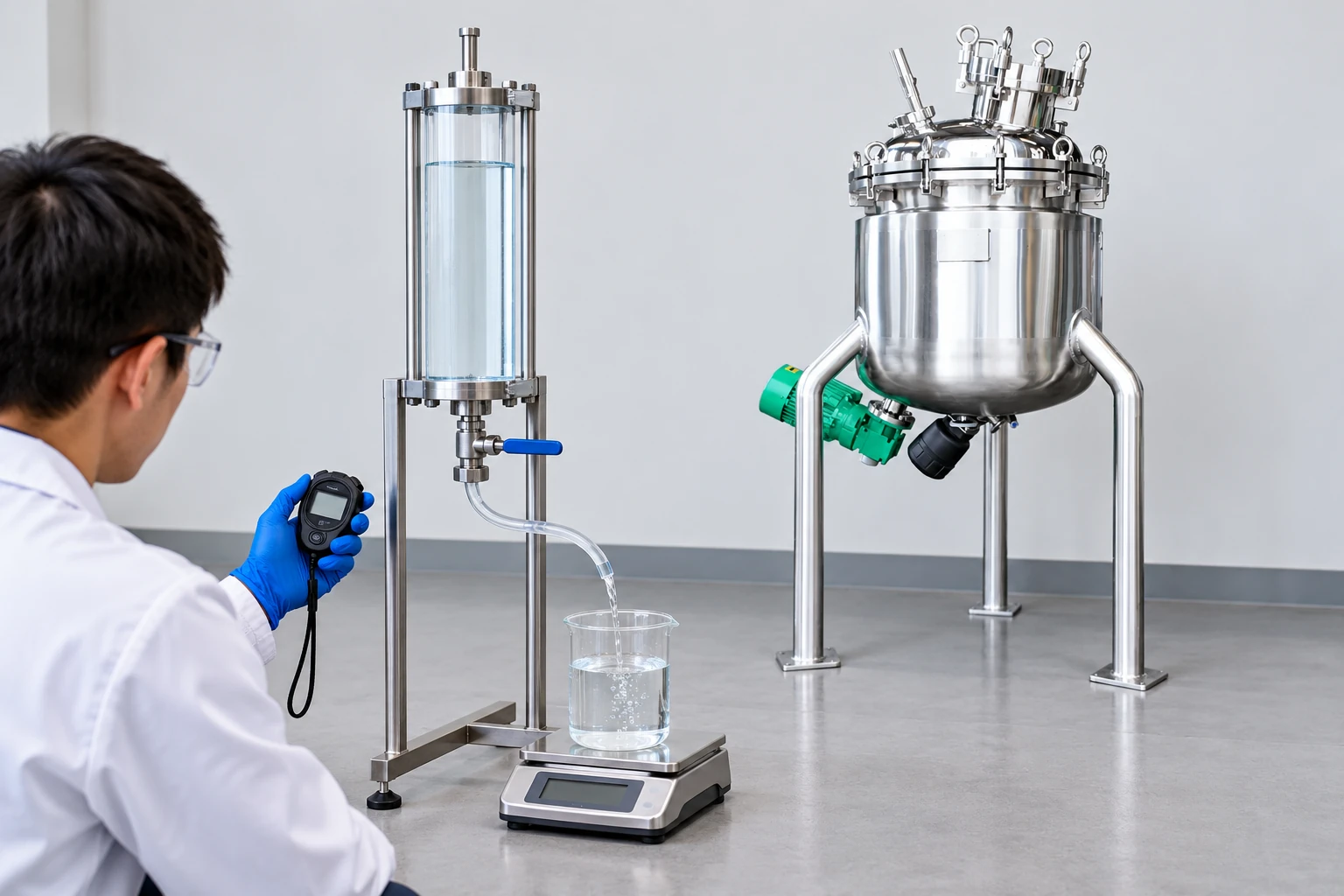
A suitable gravimetric check instead records net collected liquid mass over elapsed time, using verified density if volumetric flow is needed. Support the collection vessel independently: contact from a hose or another fixture can bias the balance. The illustrated water-only apparatus explains that measurement principle; it does not establish pump performance at the actual production backpressure or authorize an open test with a hazardous chemical.
Translate liquid flow into active chemical dose
If the stock contains a known active chemical mass per litre, multiply that concentration by the measured stock flow to obtain active mass delivery per hour. Then divide by the receiving-process flow using consistent units. Confirm that the stock concentration is expressed on the same chemical basis as the required dose; active ingredient, commercial product, and elemental equivalent can differ.
For illustration, a verified stock concentration of 20 grams per litre delivered at 15 litres per hour supplies 300 grams per hour. Into 100 cubic metres per hour, that corresponds to 3 milligrams per litre before reaction, losses, or process-specific corrections. The numbers are hypothetical. The calculation does not establish treatment effectiveness, residual concentration, or a permissible dose for any application.
Review chemical make-up tank design for solution preparation inputs and chemical containment planning for spill considerations. Both are complementary to the delivered-flow measurement.
Confirm stock preparation with a stock-dilution mass balance and an appropriate analytical check before translating measured liquid flow into active-chemical delivery.
Diagnose a result that does not match the setting
Check the measurement before adjusting the pump. An incorrect tank conversion, an uncounted return flow, or a timing mistake can resemble a pump fault. Verify valve positions and the actual process pressure. Compare the setting displayed by the controller with the signal reaching the drive. A mismatch can arise from scaling or control configuration as well as the mechanical equipment.
Air, suction restrictions, worn components, or unsuitable liquid properties can reduce repeatability. Use the manufacturer’s diagnostic procedure and isolate equipment before maintenance. Do not remove pressurized fittings or place a hand near moving components to investigate a flow problem. A test that repeatedly drifts may require a different measurement arrangement before a reliable conclusion is possible.
Set a useful recalibration schedule
Choose frequency from the process consequence, observed stability, manufacturer instructions, and applicable operating requirements. Recheck after maintenance, a change in chemical concentration, suction arrangement, discharge pressure, or control settings. A calendar interval alone does not detect a sudden change between scheduled tests. Consider appropriate operating trends and alarms alongside the periodic measurement.
Store results so changes are visible: date, operator, equipment identifier, liquid, settings, pressure, raw readings, calculated flow, repeat spread, and action taken. If the result fails, state whether production dosing was affected and how the period since the last acceptable check will be assessed. The record should support a practical decision rather than simply a calibration sticker.
Specify measurement needs when buying a dosing tank
For a compatible solution-preparation vessel, explain whether the tank will be used for mixing, storage, drawdown measurement, or several duties. Its visible product geometry does not establish a calibrated volume scale or chemical compatibility. Request the relevant documentation and a measurement arrangement suitable for the actual operating range.
Keep the approved measurement method with the equipment record so that later operators can reproduce the same conditions and compare results fairly.
Further learning: chemical feed pumps and calibration
This government operator-training video discusses chemical feed pumps, maintenance and calibration. Apply its measurement principles with the actual pump instructions, chemical properties and approved field test arrangement.
Watch Chem Feed Pumps and Calibration by Pennsylvania DEP
FAQ
Can a tank level change replace a calibration column?
Only when the installed tank’s volume-versus-level relationship and reading uncertainty are adequate for the required test. Bottom geometry, foam, agitation, and small level changes can limit accuracy.
Does a drawdown test prove the final treatment dose?
It establishes liquid delivery under the tested conditions. Stock concentration, receiving flow, chemical basis, and process response need separate verification.
Why test at more than one pump setting?
A single operating point does not establish the complete delivery curve. Relevant low, normal, and high settings can reveal non-linearity or unstable operation within the intended range.


