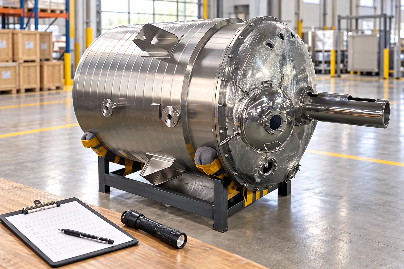
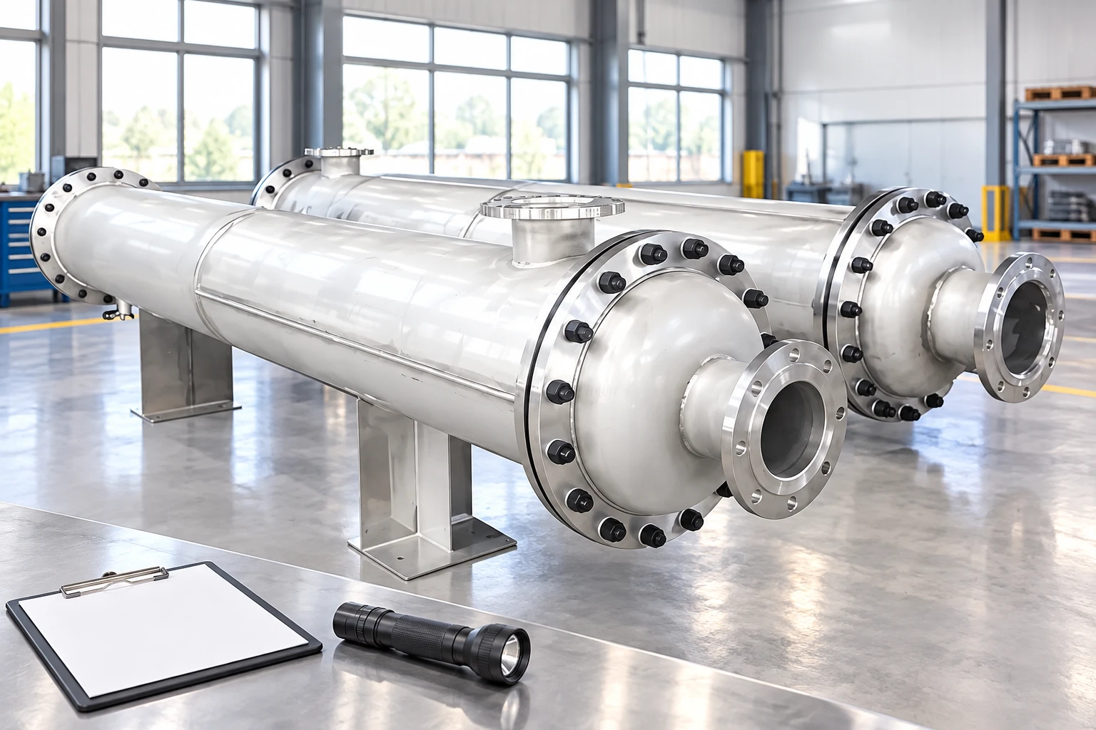
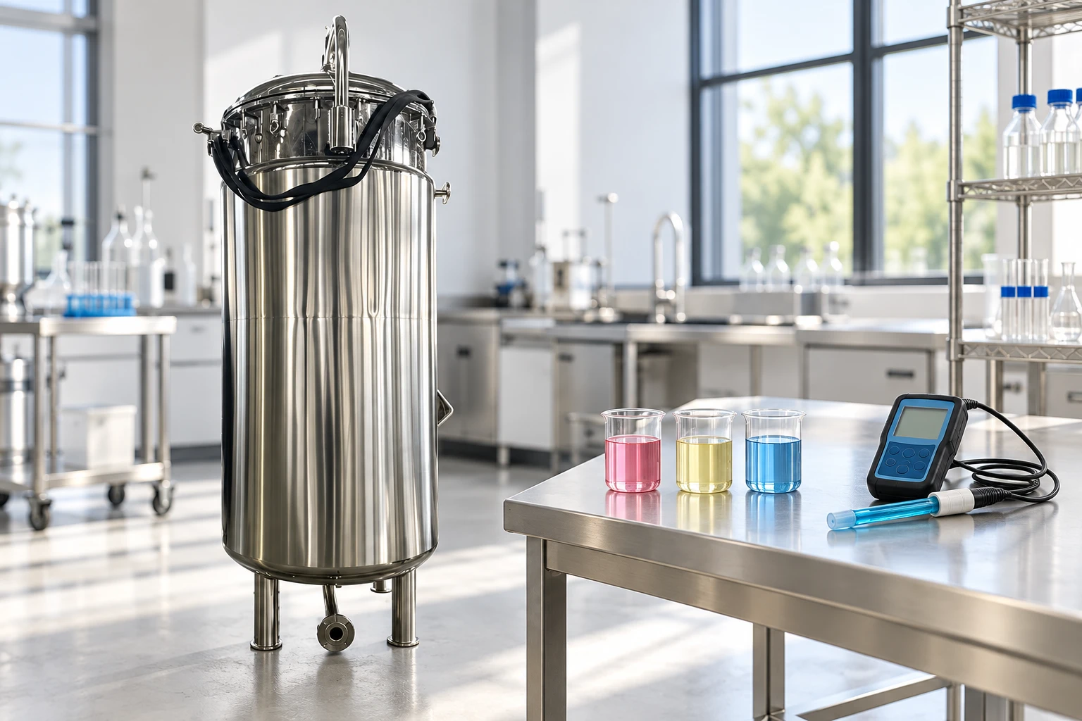
The names buffer tank and balance tank are often used loosely, but the process job should decide the equipment. One vessel may be asked to absorb a short interruption, maintain a stable feed level, or provide a controlled hold period. Those are related duties, yet they create different sizing, control, and hygiene questions.
For a useful specification, describe the mismatch that must be managed: how much flow changes, for how long, what level range is usable, and what happens when the tank reaches its limits. That approach turns a familiar label into a measurable surge-control requirement.
Part 1. Define the Process Role Before Naming the Vessel
A buffer tank commonly absorbs a temporary difference between inlet and outlet flow. It can give upstream and downstream equipment time to recover from normal variation without stopping the entire line. The word “buffer” describes a function, not a universal construction or capacity.
A balance tank is often used for a controlled inventory or level that supports a downstream operation. In some plants the term refers to a vessel that keeps a pump supplied, a filler fed, or a recirculation system stable. Other industries use the same term differently. For that reason, an RFQ should state the required process behavior rather than rely only on the name.
Ask four opening questions: what disturbance occurs, how long does it last, what flow continues during the event, and which machine is protected? The answers reveal whether a short-term surge volume is needed, whether a regulated liquid level is the primary goal, or whether two separate functions have been combined in one vessel.
Neither label guarantees product quality or sanitary suitability. If the tank holds a sensitive product, the allowable residence time, temperature, cleaning method, and mixing requirements must be defined separately. A vessel can prevent a flow interruption while still being unsuitable for the product’s hold conditions.
Part 2. Calculate Surge Volume from the Flow Mismatch
The initial buffer-volume calculation uses the flow difference over the duration of the disturbance. When inlet flow exceeds outlet flow, the liquid level rises; when outlet flow exceeds inlet flow, the level falls. A preliminary relationship is:
Surge volume = absolute flow mismatch × event duration
Use consistent units, then add a documented operating margin for normal variation and control response. For example, if an upstream process continues at 3 cubic metres per hour while a downstream process pauses for four minutes, the theoretical accumulation is 0.2 cubic metres. That result is only the starting point because the usable volume may be smaller than the vessel’s geometric volume.
| Calculation input | What to record | Why it changes vessel size |
|---|---|---|
| Maximum inlet flow | normal and upset flow | Sets the rising-level rate |
| Maximum outlet flow | normal and upset flow | Sets the falling-level rate |
| Disturbance duration | seconds or minutes | Converts mismatch into volume |
| Restart behavior | ramp, step, or uncertain | Affects recovery allowance |
| Operating-level band | low to high usable levels | Limits available surge volume |
Avoid sizing only for a single, idealized event. Include expected pauses, flow ramps, changeovers, and the time required for an operator or automatic sequence to respond. If the disturbance is outside the assumed range, define whether the line should slow, bypass, recirculate, or stop. That decision belongs in the control narrative.
| Volume term | Meaning | Typical use |
|---|---|---|
| Geometric capacity | Physical vessel volume | Equipment envelope |
| Usable surge volume | Volume between permitted operating limits | Mismatch absorption |
| High-level reserve | Volume before the high-high response | Protection and escalation |
| Low-level reserve | Volume before low-low response | Pump and downstream protection |
Part 3. Protect the Usable Range with Level Control
The theoretical surge volume is unavailable if the normal level setpoint is too close to one limit. Choose a normal operating band that leaves room for both accumulation and depletion. The arrangement should also define the instrument type, alarm points, control valve or pump response, and action when the level continues beyond the normal band.
Level control is not merely an accessory. Sensor accuracy, signal filtering, controller tuning, and actuator response affect the amount of volume that is practically available during a disturbance. A slow response can consume reserve volume before the process changes flow; an unstable response can create repeated excursions. Controls engineering should therefore review the vessel and the logic together.
Specify high, high-high, low, and low-low functions in process terms. A high alarm may notify an operator, while high-high may reduce upstream flow or stop transfer. A low alarm may indicate an approaching shortage, while low-low may protect a downstream pump. The exact actions depend on the process and must be agreed by the project team.
Part 4. Review Residence Time and Product Boundaries
Every surge vessel creates a residence time. For a stable utility fluid, that may be a minor consideration. For a food, beverage, chemical, or temperature-sensitive formulation, the time and conditions inside the tank can affect quality, cleaning, and operational limits. Do not add buffer volume without checking what it means for the product.
Document maximum and minimum expected hold times, temperature exposure, agitation need, and whether the product can stratify, settle, foam, or degrade. If the vessel also serves as a balance tank for a feed pump, the minimum level must protect the pump without creating an excessive hold time at low throughput.
Hygienic scope needs the same discipline. The 3-A Sanitary Standards provide a useful reference point for sanitary equipment discussions, but the applicable design and cleaning requirements must be defined by the project. A generic “sanitary buffer tank” is not enough information for a final selection.
Part 5. Choose a Configuration for the Actual Duty
The Mixing Tank category provides a starting point when the surge vessel also needs product movement or blending. Use it to discuss vessel material, fittings, outlet arrangement, and optional agitation, then relate each feature to the required process role.
An 800L mixing tank may be a reasonable capacity reference for an RFQ, but it should not be selected simply because the calculated surge is close to 800 litres. The usable level range, reserves, footprint, connections, and residence time may lead to a different configuration or nominal size.
Where the liquid needs defined agitation, a configurable mixing tank with agitator is the product recommendation to evaluate. Confirm the duty at both low and high operating levels and state whether the agitator is for homogeneity, suspension, or only occasional blending.
The fit boundary is clear: this article does not calculate hydraulic stability, validate a control loop, select pressure or vacuum equipment, or establish product-quality limits. Processes where safety, aseptic conditions, hazardous materials, or sensitive product quality depends on level response require detailed engineering.
For broader context, see what is a stainless steel mixing tank and the chemical mixing tank guide for industrial buyers.
Part 6. Write an RFQ and Control Narrative
Good buffer-tank RFQs describe both the vessel and the event it must handle. State inlet and outlet flows, normal and maximum mismatch, event duration, required recovery time, operating-level setpoint, allowable high and low levels, and the desired alarm or interlock actions. Include the product, density, viscosity range, temperature, solids, cleaning method, and hold-time limits.
Specify connections, available utilities, material, surface and hygienic scope, installation footprint, access requirements, instrumentation, controls interface, and documentation. Explain whether the tank feeds a pump, a filler, a mixer, or another process step. That information lets suppliers identify missing assumptions instead of guessing.
Request that quotations state nominal capacity, usable operating range, expected residual volume, level-instrument assumptions, and exclusions. Add a general arrangement drawing and a concise sequence of operation to the comparison package. A complete request can then be sent to contact YIYI for configuration discussion.
FAQs
What is a buffer tank used for?
A buffer tank is commonly used to absorb a temporary mismatch between inlet and outlet flow. Its required volume depends on the size and duration of the mismatch and the usable level range.
Is a buffer tank the same as a balance tank?
Not necessarily. A balance tank often refers to maintaining a controlled inventory or level, while a buffer tank emphasizes absorbing variation. Definitions vary, so the required function should be written into the specification.
How is buffer tank volume calculated?
Multiply the expected flow mismatch by the event duration, then review control response, operating-level limits, and appropriate process margin. The result must fit inside the usable surge volume, not merely the geometric capacity.
What level instruments are needed for a buffer tank?
The choice depends on the product and controls design. At minimum, the process team should define the normal level measurement, high and low alarms, high-high and low-low actions, and any required interface to pumps or valves.
Can a buffer tank improve product quality?
It may prevent interruptions that would otherwise affect the line, but it does not automatically improve product quality. Residence time, temperature, mixing, cleaning, and product stability still require separate review.
What should be included in a buffer tank RFQ?
Include flows, mismatch duration, usable level range, product properties, cleaning needs, hold-time limits, connections, utilities, instrumentation, control actions, and installation constraints.