

Silo level measurement should begin with the decision the reading must support: preventing overfill, maintaining a minimum reserve, or reconciling usable inventory. Radar measures distance to a reflecting surface, load cells measure supported weight, and capacitance devices respond to changes around a sensing element. Those are different observations, so choosing between them requires more than comparing advertised accuracy. For powders, uneven surfaces, changing bulk density, buildup, filling dust, and mechanical connections can dominate the result. A reliable specification defines the required quantity, the difficult operating conditions, the mounting arrangement, and how the completed system will be checked.
Define level, volume, and mass separately
A single surface-distance reading is a local measurement. Converting it to height requires a known reference position and vessel geometry. Converting height to volume assumes something about the material surface, and converting volume to mass introduces bulk density. A powder mound under an inlet or a discharge depression may make a clean, repeatable distance reading an imperfect inventory estimate. Do not label that difference a defective transmitter until the conversion assumptions are examined.
Weight measurement avoids the surface-to-volume conversion when the objective is mass, but the supported weight includes the vessel, attachments, and product. Tare must be established and maintained. Changes to connected equipment can affect the result. Meanwhile, a point-level switch answers whether material occupies its sensing location; it does not inherently provide continuous inventory. Distinguish a high-level alarm from a continuous reading in the purchase specification rather than treating either as a complete substitute for the other.
Start from the broader powder storage tank and silo RFQ guide when defining the storage duty. This article focuses on measurement selection for powders, rather than the foam and agitation conditions covered in mixing tank level measurement.
Radar: evaluate the installed measurement path
Radar equipment uses electromagnetic signals and their interaction with a target to determine distance. A noncontact arrangement avoids placing a long sensing probe in the bulk material, but it still needs an appropriate mounting location and a usable return. The installation assessment should consider the inlet stream, nearby walls, internal obstacles, and the expected surface shape. These can affect which return the instrument interprets as the product surface. Confirm suitability for the actual powder with the instrument supplier.
Request a drawing showing the nozzle, antenna location, measurement direction, and the proposed reference datum. Ask how the selected instrument handles filling conditions, weak returns, empty-vessel echoes, and material adhering near the antenna. A broad claim that radar works through dust does not establish performance for every installation. Keep raw distance, signal-quality information, and the converted process value available during commissioning so an operator can distinguish an echo problem from a conversion problem.
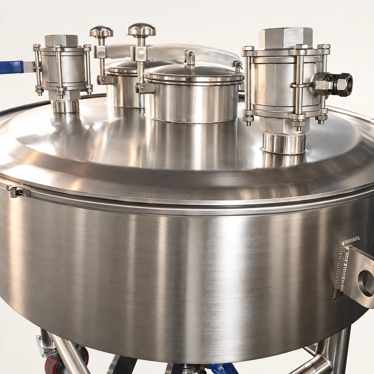
The equipment image shows the actual upper vessel envelope and fittings used as a product reference. It does not show an installed radar transmitter or establish that an existing fitting is a suitable radar nozzle. Final access, mounting clearance, pressure boundary, cleaning requirements, and instrument geometry need a project-specific drawing.
Load cells: control the complete mechanical load path
Load cells are attractive when the required output is product mass and the vessel can be supported through a controlled weighing arrangement. The difficult part is often the installation surrounding the sensors. Rigid pipework, restrained connections, a bridging support, cable tension, and unintended contact can introduce forces that the weighing system interprets as weight or that bypass the intended measurement path. A transmitter cannot compensate for every mechanical installation error.
Review supports, flexible connections, thermal movement, attached platforms, and maintenance access with the responsible structural and weighing specialists. Specify the empty-vessel condition used for tare and the method for applying known test loads. Do not assume that a photograph of support legs proves load-cell compatibility. Retrofitting an existing silo may require structural changes and a controlled shutdown; compare that effort with the inventory benefit before purchasing components.
A mass reading can still be unsuitable as the only overfill indication. Product with a lower bulk density can occupy more space at the same mass. Conversely, changing the stored recipe may alter the usable volume limit. Document whether the process needs a separate high-level device or another independent protective measure, and make that choice through the site risk assessment rather than a generic rule.
Capacitance: verify the material and buildup conditions
Capacitance sensing depends on the electrical conditions around the sensing arrangement. A device may be configured for point detection or continuous indication, so the product description must identify its intended function. Powder composition, moisture, deposits, and the vessel arrangement may affect the response. Obtain application confirmation for representative product conditions, including the extremes likely during a campaign or seasonal change.
NPTEL’s Industrial Instrumentation course provides an academic foundation for capacitance transducers and load cells. Its principles help explain the technologies; they do not certify a particular silo installation. Ask the proposed supplier how calibration will be performed, what a coating on the probe does to the output, and how an operator recognizes a fault rather than a genuine high-level condition.
A practical sample trial should include material that represents both normal and difficult batches. Record moisture condition, loose or settled state, temperature, and whether a deposit remains after discharge. If different powders will share the vessel, determine whether settings need to change between products. Include cleaning and inspection access in the decision because a sensing element that cannot be maintained conveniently may produce avoidable downtime.
Compare technologies against the required decision
| Requirement or condition | Radar assessment | Load-cell assessment | Capacitance assessment |
|---|---|---|---|
| Continuous local surface position | Check return quality and target location | Weight needs a separate geometry and density model to estimate level | Confirm continuous rather than point configuration |
| Product mass inventory | Quantify surface and bulk-density conversion error | Review tare and all mechanical load paths | Quantify the conversion assumptions and material response |
| Independent high-level indication | Review alarm architecture and common failures | Check whether mass reliably represents maximum occupied volume | Evaluate a dedicated point device and its proof-test method |
| Changing powder or moisture | Trial reflection behavior and conversion settings | Mass remains mass, but volume limits can change | Trial electrical response and buildup behavior |
| Existing rigid connections | Check measurement obstructions and access | Assess force transfer before choosing a retrofit | Check probe location and maintainability |
| Filling and discharge transients | Save raw distance and return diagnostics | Review vibration, restraint, and signal filtering | Test dynamic response and residual coating |
This table is an application-review checklist, not a performance rating or a claim that one technology is universally best. Complete it against the proposed model’s documentation, a vessel drawing, and representative material tests.
Set alarm limits from usable headroom
An alarm threshold should account for what happens after the alarm, not just where the surface is when it activates. Define filling rate, stopping delay, material remaining in the transfer path, and uncertainty in occupied volume. Explain who or what stops transfer and how the operator confirms the stopping action. For pneumatic filling, measurement is only one part of the pressure and dust-control assessment.
The HSE guidance on dust explosions in the food industry discusses overfilling and the need for suitable arrangements on pneumatically supplied vessels. Apply the guidance within the relevant industry and jurisdiction; it is not an approval for any photographed vessel or instrument. Preserve the responsibility for ventilation, isolation, pressure protection, and transfer controls in the overall project specification.
Do not plan routine manual dipping or internal inspection as an informal fallback. Access to stored bulk material can introduce serious hazards. The HSE confined-spaces guidance explains why the assessment and safe system of work must precede entry. Use external checks wherever practicable and arrange specialist procedures for work that requires entry or opening the process.
Commission with observations that expose errors
Agree on an acceptance plan before delivery. A useful test sequence documents the empty condition, several known loading increments, an operating filling cycle, a discharge cycle, and the alarm response. Record the reference observation alongside the instrument output and its diagnostic values. Test conditions should represent the site’s real operating envelope rather than an easy demonstration on an empty vessel.
For a radar system, compare the distance output with the geometry and inspect changes during filling. For weighing, apply the agreed reference loads and check zero return after unloading. For capacitance, test the defined material conditions and inspect residual deposits. Identify permitted adjustment steps, the person authorized to change settings, and the records needed after recalibration. Acceptance should include documentation and operator understanding as well as a screen displaying a plausible number.
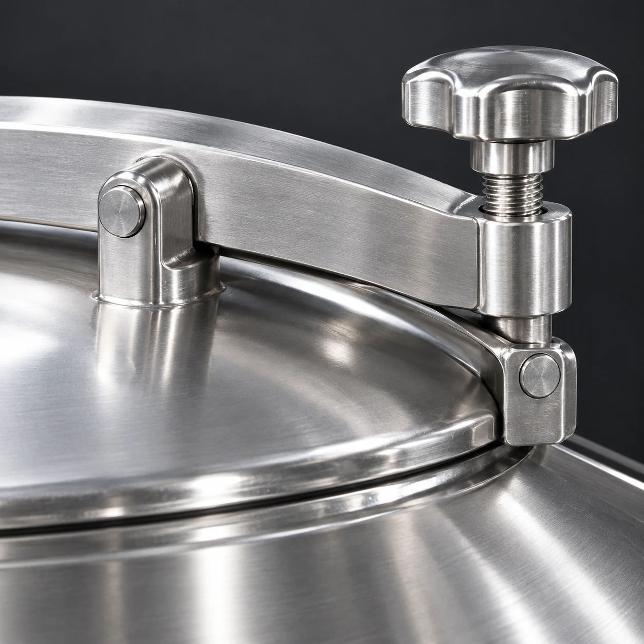
The manway and fittings illustrate access considerations only. They do not establish an electrical classification, a pressure rating, a measurement range, or a suitable sensor mounting connection. Review these requirements independently with the vessel and instrument suppliers.
Prepare a complete enquiry for the vessel and instruments
Send the stored material list, representative bulk-density range, moisture conditions, operating temperature, pressure or vacuum duty, filling method, discharge behavior, and the required inventory or alarm function. Add vessel dimensions, inlet and outlet positions, available connections, support arrangement, maintenance clearance, electrical requirements, and the site’s hazardous-area information where applicable. State how accuracy will be assessed in actual use and what reference method will be available.
YIYI’s stainless steel silo product provides a starting point for discussing the vessel envelope. Its product images establish visible equipment features only; instrument supply, mounting provisions, and weighing suitability must be confirmed for the enquiry. Also review silo hopper angle selection because surface behavior and discharge conditions affect interpretation of level readings. Request a coordinated drawing so the vessel, measurement equipment, filling controls, and maintenance requirements are reviewed together.
Educational video: capacitance transducer principles
NPTEL’s lecture explains capacitance transducers as instrumentation technology. Use it to understand why a sensing arrangement responds to its surrounding electrical conditions. It is further learning material, rather than a product recommendation or a commissioning instruction for combustible powder service.

Watch Lecture -11 Capacitance Transducers by nptelhrd
Frequently asked questions
Is radar automatically more accurate than load cells?
The technologies measure different quantities. Radar may give a repeatable local distance while a weight system may better serve mass inventory. Installed performance depends on mounting, material behavior, load paths, calibration, and the conversion used for the required process decision.
Can a high-level switch replace continuous inventory measurement?
A point device indicates whether material occupies a specific sensing location. It can support a defined alarm function, but it does not inherently show remaining inventory. Specify the required functions separately and evaluate protective independence through the site risk assessment.
What should be tested before accepting a powder silo measurement system?
Check empty and loaded conditions, representative filling and discharge behavior, diagnostic outputs, calibration records, and the required alarm action. Include difficult material conditions, mechanical connection effects, and maintenance access rather than accepting a single stable reading as proof of performance.


