

Heat exchanger tube velocity is the average speed of a fluid through the open tube area carrying that stream in one pass. Calculate it from actual flow and the active tube count, then review heat transfer, fouling, pressure loss, erosion risk, and the lowest operating flow together. There is no single velocity that is correct for every fluid, alloy, or exchanger. A useful specification defines the normal and limiting flow cases, the tube geometry, and the acceptance checks. Tube-side velocity also differs from shell-side crossflow velocity, nozzle velocity, and a cleaning-system target.
Define the area before calculating velocity
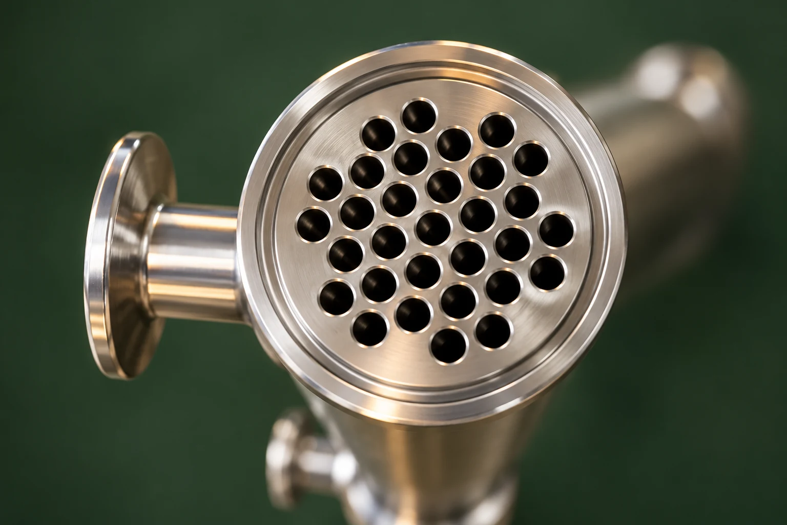
For a single-phase incompressible stream divided evenly among parallel tubes, average velocity is volumetric flow divided by their combined internal area. Use the tube inside diameter, not its outside diameter. Count the tubes available to the stream in the current pass rather than automatically dividing by the total installed tube count.
The basic relationship is v = Q / A, with A = n × π × d_i² / 4. Here v is average velocity in metres per second, Q is volumetric flow in cubic metres per second, n is the number of active parallel tubes in that pass, and d_i is tube inside diameter in metres. Convert all inputs before calculating.
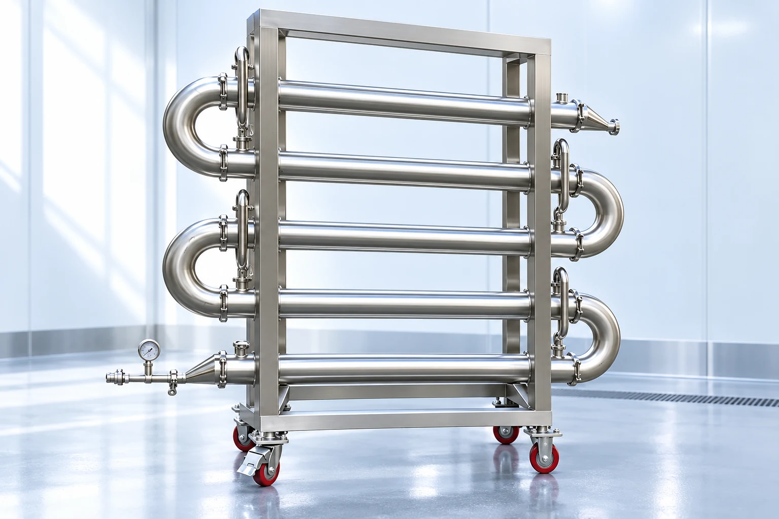
For a multipass arrangement, identify each pass on the approved drawing. Equal division of installed tubes is an assumption that needs confirmation. A sanitary rack with several visible horizontal sections may carry fluid sequentially through those sections; the exterior count does not establish the number of inner flow paths. Do not infer that geometry from a photograph alone.
Work through a transparent tube-side example
Consider an illustrative liquid flow of 18 cubic metres per hour through 100 open parallel tubes, each with a 16 millimetre inside diameter. These are assumed calculation inputs, not dimensions or operating values for a YIYI product. Assume equal distribution, one phase, and negligible density change through the exchanger.
Convert flow: Q = 18 / 3,600 = 0.005 cubic metres per second. Convert diameter: d_i = 0.016 metres. Combined area is 100 × π × 0.016² / 4 = approximately 0.02011 square metres. Average tube velocity is 0.005 / 0.02011 = approximately 0.249 metres per second.
If the same total of 100 tubes is arranged in two passes with 50 parallel tubes per pass, the calculated velocity in a pass is approximately 0.497 metres per second at the same inlet flow. That comparison assumes equal pass division and no bypass. It does not establish that the higher velocity is acceptable or that the two arrangements provide equivalent duty.
If ten of those 50 tubes are plugged, the active area falls to 40 tube paths. At the same flow the average velocity becomes approximately 0.622 metres per second, a 25 percent increase. Recalculate the thermal and hydraulic performance after plugging; restoring outlet temperature alone is insufficient evidence that the revised unit remains within its limits.
Use Reynolds number to interpret the flow
Velocity alone does not identify the flow behaviour. For Newtonian flow in a circular tube, Reynolds number is Re = ρ × v × d_i / μ, where density ρ is in kilograms per cubic metre and dynamic viscosity μ is in pascal seconds. Use fluid properties at a representative temperature and evaluate changes along the flow path where they are significant.
The University of Colorado’s LearnChemE Reynolds number explorer illustrates how density, viscosity, diameter, and speed combine. Its pipe-flow model is educational. It does not establish a guaranteed transition or heat-transfer correlation for every exchanger entrance, bend, insert, or non-Newtonian product.
For the first example, assuming density of 1,000 kilograms per cubic metre and viscosity of 0.001 pascal seconds gives Re of approximately 3,979. Those properties are illustrative assumptions. Increasing viscosity to 0.010 pascal seconds at unchanged flow lowers Re to approximately 398. This shows why a velocity copied from a water application may give a very different result with a viscous process stream.
Compare the competing effects in one review
Changing flow alters several aspects of performance simultaneously. Under suitable conditions, higher velocity can improve convective transfer and reduce some deposition tendencies. It also changes pressure loss and may aggravate wear where material, particles, inlet geometry, or operating conditions are unsuitable. It is not an automatic cure for fouling.
Use the following qualitative table to organize a supplier review. It gives no universal velocity limits because fluid composition, geometry, and material evidence have not been supplied. The LearnChemE flow resource and its interactive friction-factor diagram provide educational context for flow regime and hydraulic resistance.
| Operating situation | What to examine | Evidence or action to request |
|---|---|---|
| Low production flow | Flow distribution, thermal duty, and deposition | Rating at the actual minimum continuous flow |
| High production flow | Pressure loss, material exposure, and inlet effects | Hydraulic rating and service-specific allowable conditions |
| Increased viscosity | Reynolds number and required pumping pressure | Properties and rating at the coldest or most viscous condition |
| Tube plugging | Active area and altered pass distribution | Revised tube count, velocity, duty, and pressure loss |
| Suspended solids | Particle properties, impingement, and deposits | Review of material and geometry for the actual solids |
| Cleaning circulation | Complete cleaning circuit and return conditions | Separate cleaning validation and equipment compatibility review |
Keep the review linked to measurable operating cases. A supplier’s preferred velocity range is only useful when its assumptions match the proposed service. Request the reason for each limit and the conditions under which it applies, including whether it refers to average tube velocity or a local region.
Keep tube flow separate from shell and nozzle flow
The shell side can contain crossflow zones, baffle windows, leakage paths, and bypass regions. Dividing shell flow by the shell’s gross circular area does not capture those local velocities. Tube-side calculations cannot therefore be copied across to assess shell-side tube vibration or baffle-zone behaviour.
Nozzle velocity uses the nozzle’s own internal area. A large average tube area can coexist with a relatively small inlet nozzle, so a satisfactory tube average does not rule out a local inlet concern. Identify entrance geometry and flow distribution when reviewing an observed wear pattern or unexpectedly high pressure loss.
For a product discussion, see YIYI’s sanitary shell-and-tube multipass exchanger. The published rack images illustrate routing and connections, while the approved drawing must establish the actual internal area and pass arrangement. Ask for those dimensions and the service rating before deriving a velocity for a quoted unit.
Specify minimum, normal, and maximum operating cases
Request a rating at the lowest sustained production flow, the normal case, and the maximum expected case. Include startup and the most viscous condition if they could govern pump requirements or duty. State which outlet temperature is required in each case and whether the control system changes either stream’s flow.
Check bypass and recirculation arrangements. A plant flowmeter upstream of a bypass does not necessarily measure exchanger flow. Record the meter location and any unmeasured split. Where instrumentation cannot establish actual exchanger flow, resolve that measurement problem before attributing poor performance to an assumed tube velocity.
For detailed hydraulic boundaries, use the shell-and-tube pressure-drop guide. It addresses how to define and evaluate pressure loss. This article’s velocity calculation supplies an input to that review rather than replacing it.
Diagnose a change using more than one instrument
If an exchanger loses duty, record both stream flows, inlet and outlet temperatures, and pressure readings at defined locations. Compare them with a clean baseline at similar conditions. A change in utility temperature, product viscosity, or bypass position can explain the observation without a change in tube cleanliness.
An increasing pressure difference at comparable flow can warrant investigation, but it does not prove one specific deposit mechanism. Likewise, stable pressure loss does not establish clean heat-transfer surfaces. Review thermal and hydraulic data together and examine the equipment using the appropriate isolation and inspection procedure.
The heat exchanger fouling resistance guide explains the thermal side of this diagnosis. The bundle maintenance guide helps plan access. Confirm the construction and condition before choosing a cleaning method; a velocity increase should not substitute for finding the cause.
Set acceptance checks and a change-control rule
During acceptance, verify the installed pass arrangement, active tube count, flowmeter location, and fluid-property basis. Record the measured flow alongside duty and pressure-loss results. Calculate velocity using that documented basis rather than treating a nominal nameplate flow as the actual operating condition.
Define what requires rerating: plugging tubes, changing product concentration, substituting a more viscous utility, modifying the number of passes, or changing a bypass. Keep the revised calculation and approval with the operating records. Small geometric changes can have meaningful consequences because flow area depends on diameter squared.
For quotation, provide tube-side mass or volumetric flow, property data, temperatures, pressure-drop limits, solids information, cleaning conditions, and expected turndown. Ask the supplier for the proposed inside diameter, active parallel area, pass arrangement, and velocity in each operating case. This produces a defensible selection rather than a generic number.
The following LearnChemE video demonstrates a Reynolds-number calculation and dimensional consistency. Use it to check the relationship between flow conditions and dimensionless groups; the exchanger rating still needs its actual geometry and fluid data.
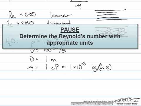
Watch Dimensionless Groups (Reynolds Number Example) by LearnChemE
Frequently asked questions
Which diameter should be used to calculate tube velocity?
Use the tube inside diameter for the tube-side fluid area. Confirm the supplied wall thickness and actual inside diameter, and count only the open parallel tubes in the pass being evaluated.
Does adding tube passes always improve an exchanger?
No. Fewer parallel paths can raise velocity at a given flow, but pressure loss, distribution, and thermal performance also change. Compare a complete rating against the actual duty and pump limits.
Is there a universal maximum tube velocity?
No. The acceptable value depends on fluid properties, solids, materials, geometry, and operating conditions. Obtain service-specific limits and a rating rather than copying a number from an unrelated application.
What happens to velocity when tubes are plugged?
At unchanged flow, reducing the active parallel area increases average velocity. Recalculate each affected pass and review duty, pressure loss, and material exposure before approving continued operation.


