

The choice between the LMTD vs NTU method depends mainly on the information available and the calculation objective. Use log mean temperature difference, or LMTD, when the terminal temperatures are known or can be established and you need to size or evaluate thermal conductance. Use effectiveness–NTU when the inlet conditions and exchanger conductance are available but the outlet temperatures must be predicted. Both methods describe the same heat-transfer problem when their assumptions, flow arrangement, and coefficient basis are consistent. Neither method replaces a pressure-drop or mechanical-design review.
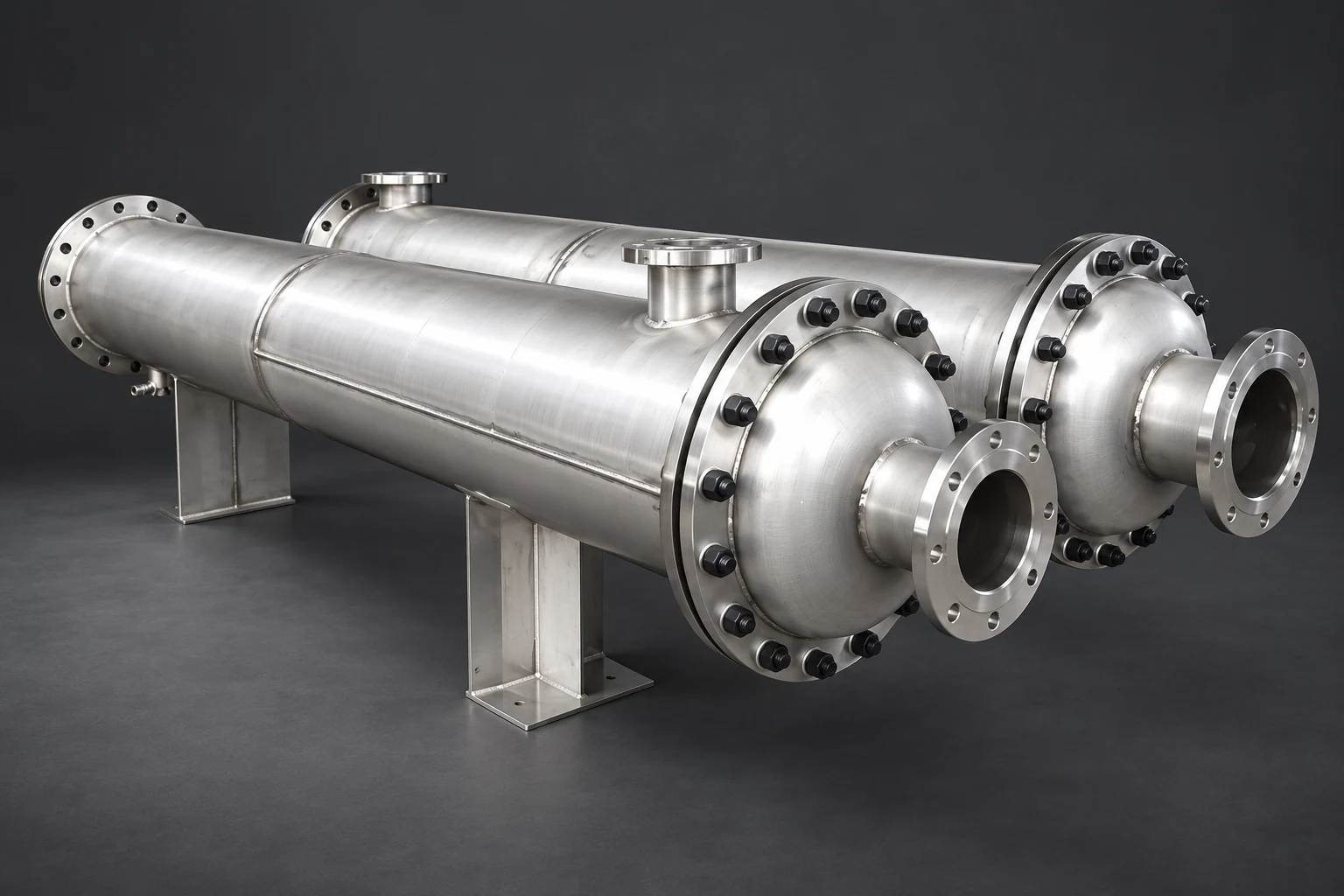
This guide compares the methods for procurement and performance analysis. For equipment context, see our tubular exchanger buyer’s guide and YIYI’s fixed-tube-sheet exchanger. A visible product configuration does not supply the missing thermal inputs for either calculation.
First define sizing, rating, and the energy balance
Sizing asks how much thermal conductance or surface area a specified duty requires. Rating asks how a particular exchanger performs at specified operating inputs. These are useful distinctions, but do not turn them into rigid labels: either method can support design work, and iterative calculations may use both. Identify the unknowns before choosing the approach.
For steady, single-phase service with negligible external loss, calculate duty from either stream as Q = ṁ cp ΔT. Mass flow multiplied by specific heat gives a heat-capacity rate, C = ṁ cp. With ṁ in kg/s and cp in kJ/(kg·K), C is in kW/K and Q is in kW. Check the two stream duties for consistency. Variable properties, significant heat loss, phase change, or transient operation require a suitable extended analysis rather than an unexplained substitution into a simple formula.
What the LMTD method needs
For an ideal counterflow exchanger, define ΔT1 = Th,in − Tc,out and ΔT2 = Th,out − Tc,in. For positive unequal differences, ΔTlm = (ΔT1 − ΔT2) / ln(ΔT1/ΔT2). If the two differences are equal, use their common value as the limit. Then Q = U A ΔTlm for the simple ideal case, or Q = U A F ΔTlm when an applicable correction factor F represents the actual arrangement.
The NPTEL multipass exchanger lecture explains the correction-factor basis and simplifying assumptions. Do not set F to unity merely because the equipment is described as shell-and-tube. Use the relevant pass configuration and calculation method. Keep U and A on the same surface-area basis, and specify whether U represents clean or fouled operation.
What the effectiveness–NTU method needs
Define Cmin as the smaller stream heat-capacity rate, Cmax as the larger, and Cr = Cmin/Cmax. The maximum possible duty for the usual two-stream model is Qmax = Cmin(Th,in − Tc,in). Effectiveness is ε = Q/Qmax. The number of transfer units is NTU = U A/Cmin. An appropriate relationship ε = f(NTU, Cr, arrangement) gives effectiveness, after which duty and the outlet temperatures follow from energy balances.
The NPTEL effectiveness–NTU explanation describes why this approach is useful when outlet temperatures are initially unknown. The relationship must match the actual geometry and mixing assumptions. A counterflow expression cannot be transferred unchanged to parallel flow, crossflow, or every multipass configuration. The conductance U A also needs a defensible value; NTU does not eliminate uncertainty about the coefficient.
Compare the methods before opening a calculator
The table is a decision aid based on the cited educational relationships. It does not imply one method is inherently more accurate. Accuracy depends on inputs, model suitability, and whether the resulting thermal case respects the actual equipment and operating limits.
| Decision | LMTD approach | Effectiveness–NTU approach |
|---|---|---|
| Terminal temperatures known | Directly calculates mean driving difference | Can check effectiveness and conductance consistency |
| Outlet temperatures unknown | Often requires iteration or additional constraints | Predicts duty from inlet conditions and conductance |
| Required conductance | Obtain U A from duty and corrected driving difference | Obtain NTU from desired effectiveness and capacity ratio |
| Flow arrangement | Select appropriate terminal pairing and correction | Select the matching effectiveness relationship |
| Shared uncertainty | Coefficient, properties, fouling, and measured temperatures | Coefficient, properties, fouling, and inlet/flow data |
| Separate checks | Pressure loss, material limits, mechanical design | The same checks remain necessary |
Work one case using LMTD
Consider an illustrative ideal counterflow exchanger with hot inlet 80 °C, cold inlet 20 °C, hot-side capacity rate 2 kW/K, cold-side capacity rate 1 kW/K, and a target duty of 40 kW. The hot outlet is 80 − 40/2 = 60 °C. The cold outlet is 20 + 40/1 = 60 °C. Equal outlet values do not imply zero driving force throughout the exchanger because those outlets are at opposite ends.
The terminal differences are 80 − 60 = 20 K and 60 − 20 = 40 K. LMTD is therefore 20/ln(2), approximately 28.85 K. The required conductance is U A = 40/28.85, approximately 1.386 kW/K for this ideal model. This is conductance, not area. A numerical area would require a justified U on a stated area basis. None of these values is a rating of a YIYI product.
Check the same case using NTU
Here Cmin = 1 kW/K, Cr = 0.5, and Qmax = 1 × (80 − 20) = 60 kW. The desired effectiveness is 40/60, or two-thirds. With U A = 1.386 kW/K, NTU is approximately 1.386. For ideal counterflow with Cr ≠ 1, ε = [1 − exp(−NTU(1 − Cr))] / [1 − Cr exp(−NTU(1 − Cr))]. The exponential term is approximately 0.5, giving ε approximately 0.667.
That predicts about 40 kW and the same 60 °C outlet temperatures. The agreement checks the arithmetic and shared assumptions. It does not prove the physical exchanger has that conductance or that the proposed fluids can meet allowable pressure losses. The University of Illinois heat-exchanger lecture notes provide additional academic treatment of the two methods and their assumptions.
Know when the simple comparison stops applying
The equations above assume steady operation and a model with consistent stream properties and conductance. If viscosity changes substantially through the exchanger, a single coefficient may not represent every section adequately. Boiling or condensing duties also need suitable treatment of phase-change regions and pressure effects. Do not present a constant-property calculation as a complete rating for such service.
Review local driving differences and temperature profiles when a case approaches a thermal limit. Mixing, bypasses, and pass arrangements can make the simple ideal comparison misleading. If a software result differs from a hand calculation, compare the model inputs and geometry before assuming the software or arithmetic is wrong. Ask the analyst to document corrections, property methods, fouling resistance, and the meaning of each reported output.
Keep thermal performance connected to hydraulics
Increasing area or conductance can alter flow distribution, velocity, or pressure loss depending on the design change. More tubes, longer tubes, extra passes, and different diameters do not have equivalent hydraulic effects. A thermal calculation should therefore be accompanied by both-side pressure-drop estimates at the specified operating range. The pump and process limitations can decide whether a mathematically satisfactory thermal case is useful.
Maintenance also matters. An arrangement that meets the nominal duty but cannot be inspected or cleaned as intended may degrade beyond the original assumptions. Use the bundle maintenance access guide for complementary questions. For coefficient assumptions, review our fouling causes guide rather than treating fouling as an unexplained margin added after sizing.
Avoid the most common comparison errors
Use the correct temperature pairings and consistent units. Confusing a single terminal approach with LMTD can produce a misleading conductance requirement. Mixing W and kW changes a result by a factor of a thousand. Using a coefficient based on outside area with an inside surface area introduces another error. Retain the coefficient definition with the calculation instead of copying a number from a generic table.
Do not compare a clean LMTD sizing case with a fouled NTU rating and attribute the different duty to the method. Likewise, changing flow arrangement between the two calculations changes the problem. When terminal differences nearly coincide, handle the LMTD limit carefully rather than evaluating a numerically unstable expression. Near thermal limits, small measurement errors can substantially affect inferred conductance; report uncertainty and avoid unsupported precision.
Use a simulation to clarify the relationships
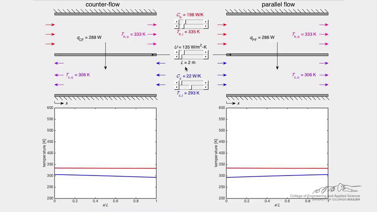
The LearnChemE video below is a neutral educational simulation of exchanger behavior. It helps connect stream inputs, duty, and temperature outputs. It does not provide a project-specific coefficient or validate the mechanical suitability of a product. Use it to understand the variables before reviewing a supplier’s calculation, then return to the approved arrangement and measured or specified operating conditions.
Watch Heat Exchanger (Simulation) by LearnChemE
Ask for an auditable supplier calculation
An effective RFQ states fluid identities and relevant composition, inlet conditions, available flow ranges, target outlet condition or duty, design conditions, allowable pressure losses, material requirements, and the cleaning plan. Identify uncertainty explicitly. If one flow is not measured, mark it as an estimate and request a sensitivity case instead of treating it as a reliable baseline.
Ask the supplier to report conductance and its basis, clean and fouled assumptions, flow arrangement, pressure losses, and operating alternatives. For acceptance testing, agree sensor locations, calibration, steady conditions, and tolerances. A report should let another engineer reproduce the energy balance and understand why the selected model fits the equipment. This is more useful than a calculator screenshot with unnamed temperatures and no property basis.
Frequently asked questions
Is NTU more accurate than LMTD?
Neither is inherently more accurate when they model the same duty with consistent inputs and assumptions. Differences usually reflect geometry, coefficients, properties, fouling assumptions, or calculation errors. Choose the method that suits the knowns and unknowns.
Can NTU determine area without a heat-transfer coefficient?
No. NTU gives conductance relative to the smaller heat-capacity rate. Converting conductance to area requires an appropriate overall coefficient on a defined area basis. The coefficient must be supported by the service and geometry.
Why can both outlet temperatures be equal in counterflow?
The outlets lie at opposite ends. Equal outlet values can coexist with positive terminal driving differences. Check the complete temperature pairing and energy balance rather than applying a parallel-flow interpretation.
What must accompany either thermal method?
Include pressure-loss limits, fluid properties, fouling assumptions, material and mechanical requirements, maintenance access, and a testable performance basis. A satisfactory thermal calculation alone is insufficient for purchasing equipment.


