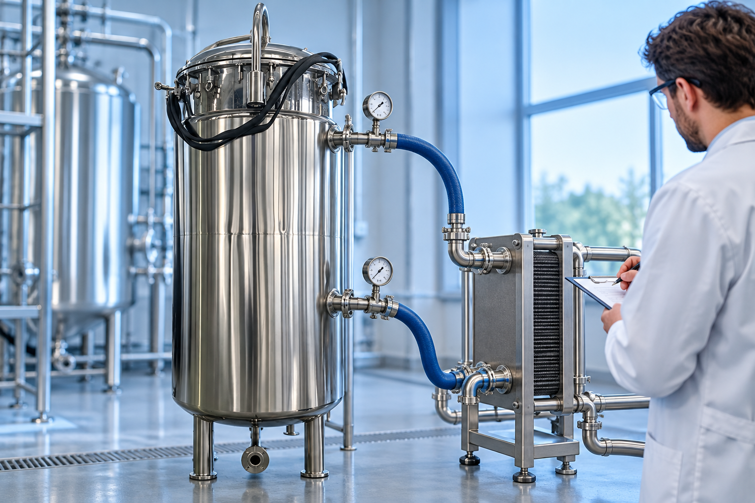
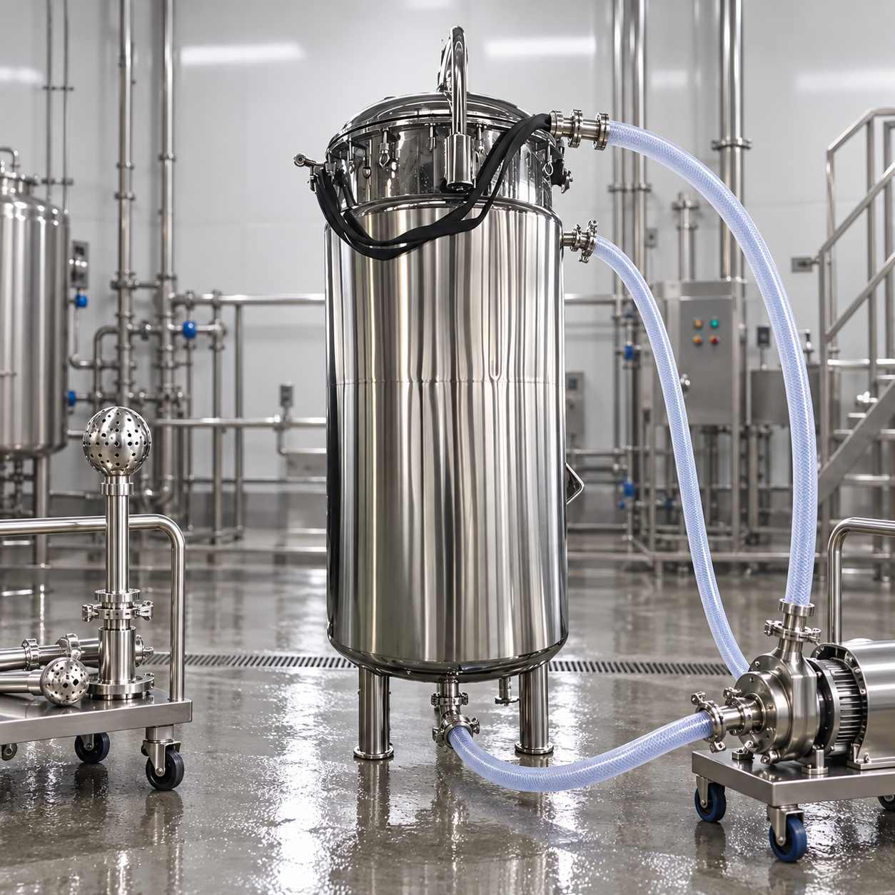
A half-pipe coil jacket is usually favored when a reactor needs higher utility pressure, stronger external reinforcement, or controlled flow through a defined spiral path; a conventional jacket is often simpler when utility pressure is moderate and broad, economical heat-transfer coverage is the priority. Neither design is universally better. Selection should compare required heat duty, utility pressure and temperature, allowable pressure drop, circulation rate, vessel diameter, wall temperature limits, fatigue, cleanability, fabrication inspection, and lifecycle maintenance. The reactor manufacturer and process engineer must rate the vessel and jacket together for all operating and upset cases.
What the two jacket types actually are
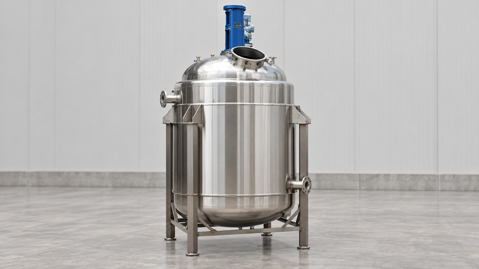
A conventional jacket forms an annular space around the vessel shell. It may be a simple full jacket, a dimple jacket, or a divided arrangement with internal baffles or multiple zones. Utility flows through the space and transfers heat across the reactor wall. The design can provide broad coverage and a relatively clean exterior, but flow distribution must be considered because wide annular spaces can permit bypassing or low-velocity regions.
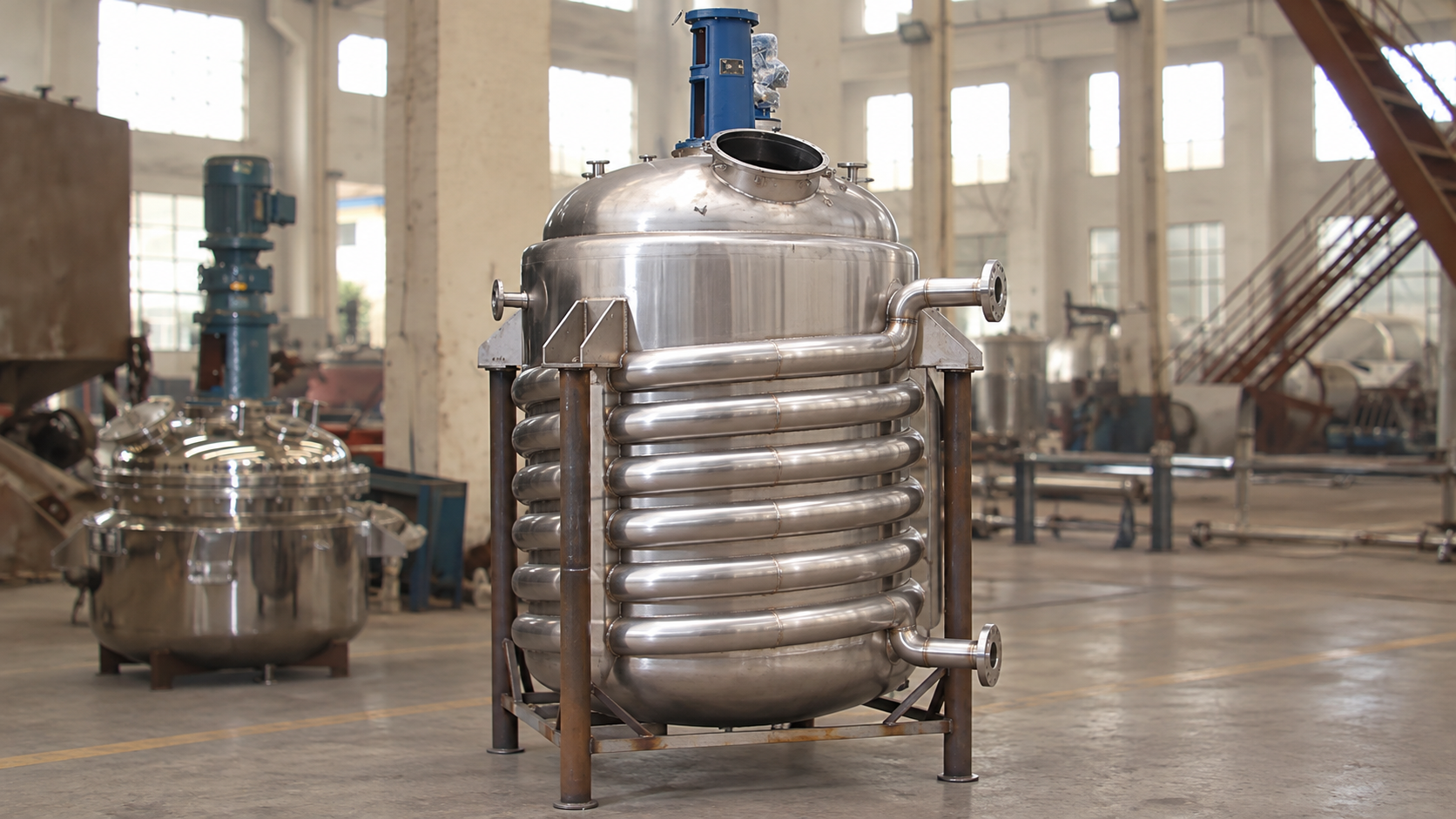
A half-pipe coil is made by welding a split pipe or formed channel helically around the vessel. The channel creates a constrained flow path with a smaller hydraulic cross-section. That geometry can support higher velocities and may permit higher jacket-side design pressure than a large conventional annulus, depending on mechanical design. It also adds weld length, exterior complexity, and inspection considerations.
Start with the process heat duty
Define heating, cooling, reaction heat removal, controlled addition, hold, crystallization, and cleaning cases separately. Calculate sensible heat, reaction heat, phase change, agitation input, and heat loss where relevant. State the required heat-up or cool-down time and the maximum acceptable wall temperature. A jacket type cannot be selected responsibly from vessel volume alone.
For exothermic batches, evaluate the credible peak rate of heat release, not just the average batch duty. Viscosity and mixing change the process-side coefficient, sometimes enough that improving jacket-side flow has little effect. The limiting resistance may be inside the vessel, in the wall, or in fouling rather than in the jacket utility film.
| Decision factor | Half-pipe coil | Conventional jacket | Buyer question |
|---|---|---|---|
| Utility pressure | Often suited to higher pressure with a compact channel | May require thicker construction or stays as pressure rises | What are design and operating pressures? |
| Flow path | Defined helical route and higher local velocity | Broad annulus; distribution depends on nozzles and baffles | How is flow distribution demonstrated? |
| Pressure drop | Can be higher through the long channel | Can be lower, but bypassing is possible | What pump head and flow are available? |
| Fabrication | Long external welds and more complex inspection | Smoother exterior and simpler insulation envelope | What welding and examination are specified? |
| Zoning | Helix can be split into circuits | Can be divided into independent jacket zones | Must lower zones operate at partial fill? |
Compare heat-transfer performance correctly
Heat-transfer capability depends on area, overall coefficient, and mean temperature difference. Jacket geometry influences the utility-side coefficient and usable area, but it is not the only factor. Agitator performance, batch viscosity, solids, wall material and thickness, fouling, utility properties, and condensation behavior can dominate. Ask for the thermal calculation with clearly stated assumptions rather than a claim that one jacket is “more efficient.”
Half-pipe flow can create useful turbulence at a given circulation rate, but its long path may impose substantial pressure drop. A conventional jacket can cover a large area, yet poor distribution can leave stagnant zones. For steam, condensate drainage and venting of air are essential. For liquid utilities, nozzle location, baffles, circuit length, and pump curve matter. The correct comparison uses the installed utility system, not an isolated coefficient.
Review pressure, vacuum, and mechanical loads
The reactor shell sees combinations of internal pressure, external pressure or vacuum, jacket pressure, thermal gradients, support loads, nozzle loads, and agitator loads. Jacket pressure can change shell buckling behavior, while the half-pipe attachment may provide local reinforcement but also creates many welded details. The mechanical design must use the applicable code and actual load combinations.
Consider startup and shutdown sequences. Pressurizing a jacket around an evacuated vessel can create a severe external differential. Trapped liquid can thermally expand when isolated. Steam can collapse into vacuum as it condenses. Specify pressure relief, vacuum protection, drains, vents, expansion accommodation, and safe isolation for both vessel and jacket circuits.
Consider fatigue and wall-temperature control
Repeated batches expose the reactor to thermal cycles. Rapid utility changes can create local gradients, particularly near inlets and at the leading edge of a circuit. State the expected number of cycles, temperature range, ramp rates, and abnormal transitions. A design that passes a static pressure calculation may still need a fatigue assessment.
Temperature-sensitive products may require limits on utility temperature or wall-to-bulk temperature difference. High-pressure steam can deliver heat quickly but may overheat material near the wall when mixing is poor. Zoning, controlled utility mixing, staged ramps, and adequate agitation can be more important than maximum jacket rating.
Evaluate cleaning, insulation, and maintenance
The process side must remain drainable and cleanable regardless of jacket choice. On the utility side, provide low-point drains, high-point vents, flushing connections, and water treatment appropriate to the utility. Scale, corrosion products, or degraded thermal oil reduce performance and can plug narrow passages.
A conventional jacket generally presents a simpler exterior for insulation and cladding. A half-pipe coil creates contours that require careful insulation detailing and may complicate external inspection. Conversely, individual half-pipe circuits can make flow paths more explicit. Ask how welds, leak tests, repairs, and periodic examination will be performed after insulation is installed.
Check partial-fill operation
If the reactor runs multiple batch sizes, map liquid level against jacket coverage. Heating an upper jacket zone above the product can waste energy, create hot surfaces, and increase vapor generation. Cooling only below liquid level may be desirable, but zoning adds valves, controls, drains, and operating steps. Define minimum and maximum working volumes before selecting circuit boundaries.
Agitator immersion and circulation at low level also affect heat transfer. A jacket can be mechanically adequate while the process remains poorly mixed. The existing viscous batch control guide explains why process-side mixing must be considered with thermal design.
Authoritative engineering context
De Dietrich’s comparison of half-coil and conventional jackets describes the construction distinction and typical pressure implications. The University of Colorado Boulder’s LearnChemE heat-transfer resources explain overall coefficients, temperature driving force, and exchanger calculations. These references are educational inputs, not a substitute for the vessel maker’s code calculation and project thermal rating.
RFQ checklist
- Working and total volume, liquid-level range, geometry, and agitator arrangement.
- Batch steps, heat duty for every case, target times, and permitted wall temperature.
- Process density, viscosity versus temperature, solids, fouling, corrosivity, and cleaning media.
- Utility type, composition, supply and return temperatures, flow, pressure, available pump head, and seasonal limits.
- Vessel and jacket design pressures and temperatures, vacuum cases, cycles, and relief basis.
- Applicable code, materials, corrosion allowance, welding, examination, testing, insulation, and documentation.
- Required zones, control philosophy, valve fail positions, drain and vent strategy, and maintenance access.
The chemical reactor product page shows the relevant stainless vessel family, while the reactor overview provides the broader equipment context. Also review the jacketed reactor heating and cooling guide and batch reactor sizing guide before issuing the thermal datasheet.
How to compare vendor proposals
Normalize each quotation to the same process cases and utility limits. Compare effective area, clean and fouled overall coefficients, circuit count, flow per circuit, velocity, pressure drop, design pressure, shell thickness, jacket attachment, weld examination, insulation scope, and guaranteed heat-up or cool-down time. A larger stated area is not automatically better if flow distribution or process-side resistance controls.
Ask each vendor to identify the controlling case and the sensitivity to lower utility flow, warmer cooling water, higher viscosity, and fouling. Confirm that the quoted circulation pump can deliver the required flow at the calculated system head. Close discrepancies between the thermal calculation, mechanical drawing, nozzle schedule, and control narrative before purchase.
Commissioning checks after installation
Before processing product, flush the utility circuit, verify vents and drains, confirm valve travel and fail positions, and compare pump flow and pressure with the approved hydraulic calculation. Pressure-test and leak-test using the specified procedure, then restore insulation without concealing unresolved defects. Check that condensate can leave steam zones and that liquid circuits do not trap gas.
During a water or approved commissioning batch, trend product temperature, jacket inlet and outlet temperatures, utility flow, pressure, agitator speed, and time. Compare the measured response with the vendor curve across at least one heating and one cooling step. Differences may reveal air binding, reversed connections, insufficient flow, sensor placement errors, or unexpected process-side resistance. Preserve the baseline for future fouling and performance reviews.
Educational video
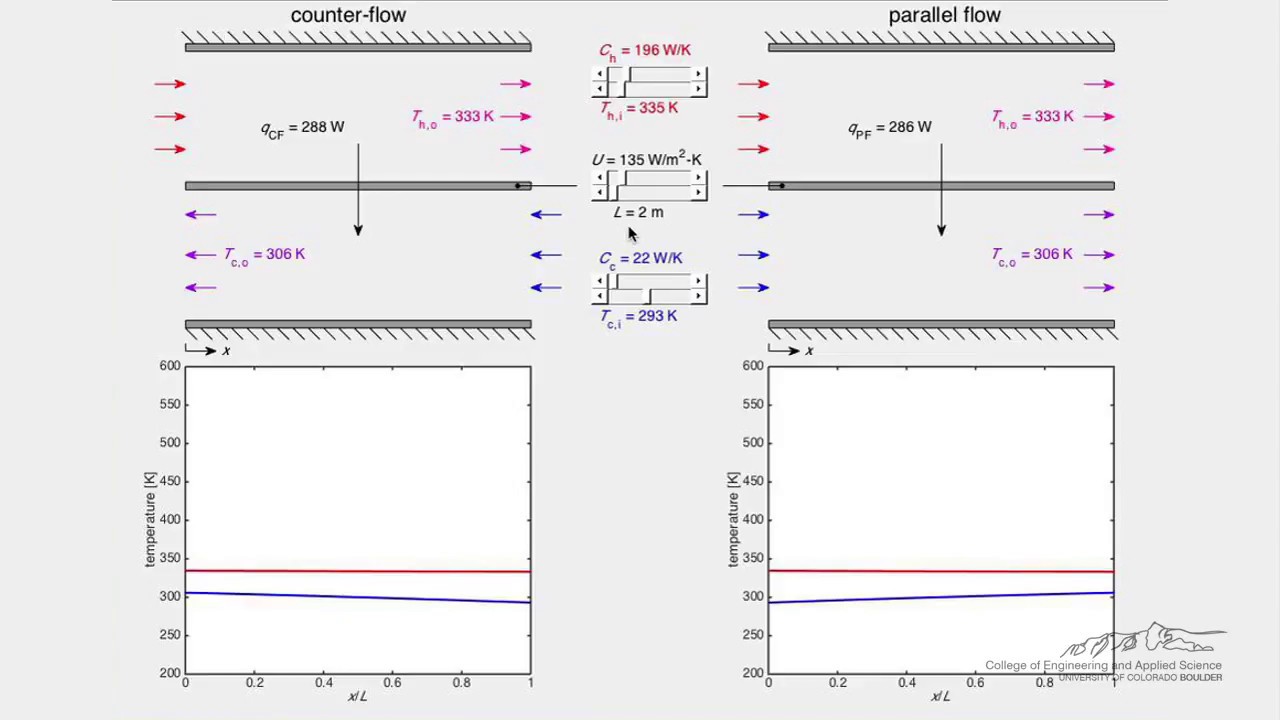
This LearnChemE simulation from the University of Colorado Boulder illustrates the temperature profiles and driving forces that underpin jacket and exchanger calculations.
Frequently asked questions
Does a half-pipe jacket always transfer more heat?
No. It can improve utility-side velocity, but total performance also depends on area, pressure drop, utility conditions, mixing, viscosity, wall resistance, fouling, and temperature driving force.
Which jacket is better for high-pressure utility?
A half-pipe coil is often attractive for higher utility pressure, but the final choice requires a code-based mechanical and thermal design for the specific vessel.
Can one jacket design serve every batch size?
Only after checking liquid level, wetted area, agitation, wall temperature, zoning, control, and drainability across the full operating range.