

CIP return pump selection starts with the cleaning circuit’s actual return conditions: liquid flow, discharge head, temperature, entrained air, remaining product, and the changing level at the collection point. A pump that handles steady clean water can perform very differently when a vessel drains in bursts or a hot rinse approaches the pump with little available suction pressure. Select the return pump against those changing conditions, then verify drainage and cleaning results in the installed system. The equipment name alone does not establish an allowable air fraction, dry-running capability, hygienic certification, or cleaning performance.
Define the return duty before choosing equipment
Draw the route from each cleaned vessel or pipe circuit to the recovery tank, drain, or treatment system. Identify whether the pump receives liquid directly from a vessel outlet, from a shared collection pot, or through a long return line. Record elevation, pipe bore, fittings, valves, strainers, and the discharge destination. These details determine the hydraulic duty and reveal places where liquid can accumulate after the cycle.
The supply pump and return pump have different jobs. Supply equipment must deliver the cleaning flow required by the process. Return equipment must remove that liquid reliably under the receiving conditions. Matching motor power or connection size between the two pumps is therefore an unreliable selection method. Also separate the liquid recovery requirement from the air-handling requirement: the same volumetric number cannot describe both without a defined reference condition.
For background on evaluating pumps as part of a complete circuit, use the US Department of Energy pumping-system resources. Their system approach supports reviewing piping, control and operating demand together; it does not certify a particular CIP pump.
Calculate liquid flow and required head separately
Establish minimum, normal and peak liquid return flow. Use measured supply flow and the sequence of active spray devices or cleaned branches where available. If several circuits can return simultaneously, describe that operating combination explicitly. A peak flow estimate based on all installed branches may be excessive when the control system prevents concurrent cleaning, while using one branch can undersize an unrestricted shared return.
Calculate discharge head from the elevation difference, pressure at the destination, and friction losses along the return path. Use the relevant liquid density and viscosity. Do not add a suction pressure deficit to a discharge requirement without using a consistent pressure balance. A vacuum at the inlet affects the available suction condition and needs its own assessment.
As an illustration of units, lifting a liquid between two open vessels with a six-metre elevation difference contributes six metres of static head. Pipe losses add to this figure at the specified flow. This is a calculation example, not a suggested CIP design or a performance claim for the pictured pump. A pressurised destination adds another term; a changing recovery-tank level can alter the duty during the cycle.
Account for air and intermittent drainage
A return line can carry liquid slugs, air pockets and foam, especially while a vessel empties. Ask the supplier how the proposed design handles this mixture and what operating limits apply. An air-handling description should identify liquid temperature, inlet pressure, duty duration and the test conditions behind the claim. A statement that a pump is self-priming does not establish that it can run indefinitely without liquid.
Check whether a receiving pot or controlled level provides a more stable inlet. That change can improve operation but also adds a vessel to clean, inspect and drain. Its internal arrangement, overflow protection, usable volume and level-control response belong in the equipment review. Avoid solving an air problem by creating an unvalidated product-retention pocket.
Return capacity should prevent unacceptable pooling in the cleaned vessel. It should also fit the recovery system’s ability to accept flow. Excessively aggressive withdrawal may repeatedly uncover the inlet or destabilise a collection-pot level. The correct operating sequence combines pump control, valve position and observed drainage rather than relying on a permanently high speed.
Review temperature and suction pressure together
Hot liquid has a higher vapour pressure than colder liquid of the same composition. At a restricted inlet, that can reduce the margin available before vapour forms. Examine the lowest liquid level, highest permitted return temperature, longest suction route and condition of any strainer. A curve supplied for a different fluid or speed is insufficient to settle this review.
The NPTEL lesson on pump characteristics and NPSH explains the distinction between suction head and vapour-pressure head. Apply that principle with supplier data for the selected pump. Confirm the applicable suction requirement and margin; do not transfer a centrifugal-pump criterion uncritically to a different air-handling design.
Locate temperature and pressure measurements where they describe the pump inlet, not a distant part of the plant. Record whether a pressure reading is absolute or gauge. Suction performance assessed using an unidentified pressure reference can appear satisfactory while the actual inlet condition is inadequate.
Use a practical selection checklist
| Duty question | Information to provide | Verification required |
|---|---|---|
| Liquid return demand | Minimum, normal and simultaneous peak flow | Pump performance at the stated liquid properties |
| Hydraulic route | Elevation, pipe dimensions, fittings and destination pressure | Head calculation and operating-point review |
| Intermittent return | Drain sequence, receiving-pot level and air entrainment | Supplier limits and an installed drainage trial |
| Hot rinse | Highest temperature and lowest inlet pressure | Suction assessment for the actual fluid and speed |
| Residual product | Expected solids, foam and carryover | Passage, seal and cleaning compatibility |
| Maintenance access | Removal space, lifting route and isolation points | Safe servicing and practical seal replacement |
This is a decision table rather than a list of universal limits. Values such as permissible solids size, suction lift and air content must come from documented equipment data and the project review. Keep the table with the request for quotation so different suppliers receive the same duty definition.
Check residues, seals and wetted materials
The return pump may see more than cleaning solution. The first displacement or rinse can contain concentrated product, particles, fats or viscous material. Identify the worst credible residue rather than defining the fluid as water throughout the entire cycle. Describe particles by size, hardness and concentration; describe viscosity at the relevant temperature rather than at storage temperature alone.
Confirm compatibility of the casing, seal faces, elastomers and any other wetted components with both product residues and the full cleaning sequence. A stainless casing is only one part of that assessment. Chemical concentration, contact time and temperature can change seal suitability. Request the material list and permitted operating envelope, including startup, flushing and shutdown conditions.
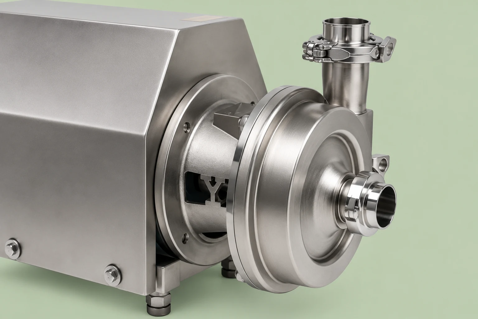
For food processing, 21 CFR 117.40 on equipment and utensils provides a useful regulatory reference for cleanability and maintenance. Applicability depends on the facility and market. It does not mean that a product photograph establishes compliance or that one pump choice validates the complete cleaning process.
Specify control and protection for the whole cycle
Describe how the return pump starts, stops and changes duty during pre-rinse, detergent circulation, intermediate rinse and final drainage. A level signal may control intermittent collection-pot service; a circuit permissive may prevent operation before the return valve opens. Identify the response to loss of liquid, blocked discharge, high temperature, seal-service failure and a full recovery tank.
Define which alarms stop the cleaning sequence and which require operator intervention. An alarm that merely sounds while contaminated liquid continues into a recovery vessel may not protect the process. Equally, an abrupt stop can leave hot cleaning solution trapped in equipment. The operating response needs a process review with the people responsible for the plant.
Where a positive-displacement design is proposed, specifically review overpressure protection. Where a centrifugal design is proposed, examine permitted low-flow operation and any gas-handling limitations. Do not copy one pump family’s operating procedure to another simply because both are used in CIP service.
Prove return performance during commissioning
Prepare an acceptance sequence that includes the most demanding approved route and realistic drainage transitions. Observe return flow, vessel level, suction condition, discharge pressure, temperature, vibration and seal condition. Verify the measurement range before interpreting the readings. A flow instrument configured for a full liquid pipe may give misleading results during an aerated return.
Check where liquid remains after the final drain. A pump can meet a flow target while the piping layout retains pockets. Record the observed condition at collection points and low sections, then decide whether piping or control changes are required. Cleaning effectiveness and drainage are related but separate acceptance questions.
Agree on the evidence needed for release: instrument records, duty confirmation, alarm tests, supplier operating instructions and an approved cleaning assessment. Water-only trials help establish basic hydraulic operation, but they cannot represent every chemical, temperature, foam or residue condition. List any untested conditions as open items rather than treating a single successful trial as universal proof.
Related equipment and further learning
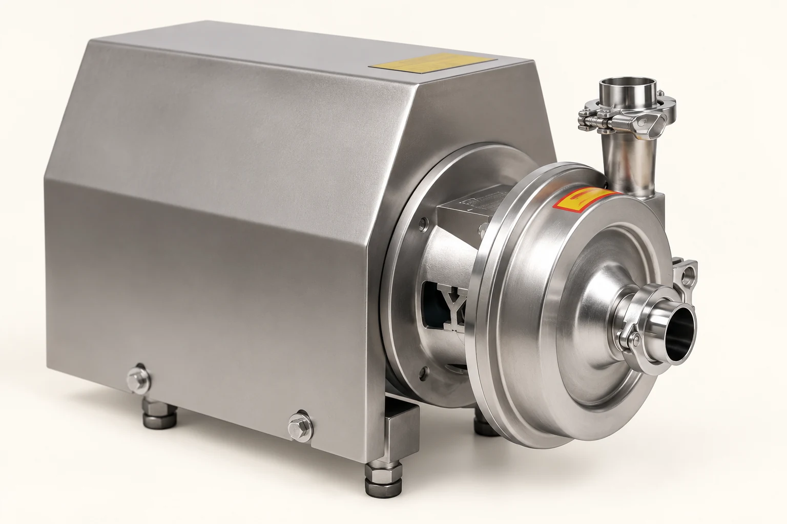
The website’s CIP return pump product page is a starting point for discussing the actual equipment configuration. Send the documented duty and ask for a confirmed performance envelope. This article makes no independent claim about that pump’s capacity or certifications.
For the surrounding process, review the food mixing tank cleaning guide, fermenter CIP spray-device selection, and mixing tank drainability. These address cleaning demand and drainage features that a return pump alone cannot correct.
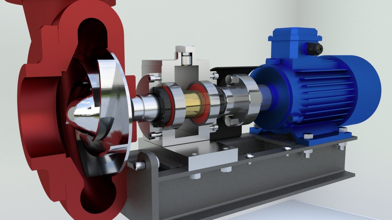
The following independent educational animation explains centrifugal pumping and priming. It supports understanding the basic liquid-pumping mechanism; it is not a demonstration of the pictured CIP equipment’s air-handling performance.
Watch How does a centrifugal pump work? by Hydraulic and pneumatic systems
Questions buyers commonly ask
Should the return pump have the same rated flow as the supply pump?
Start from the actual return demand and simultaneous operating circuits. Then review receiving conditions, head, intermittent flow and air entrainment. Equal nominal ratings do not guarantee reliable return operation because supply and return duties differ.
Does self-priming mean the pump can run dry?
No general dry-running allowance follows from that description. Ask the supplier for permitted priming conditions, seal requirements and maximum approved exposure without liquid. Include the protection and recovery sequence in the control specification.
What should be included in a CIP return pump enquiry?
Provide liquid flow range, route drawing, temperature, fluid properties, residues, air conditions, inlet level range, discharge pressure, cleaning chemicals and available utilities. Include commissioning criteria and request supplier confirmation of the complete operating envelope before selecting the final configuration.


