Blending tank mixing time calculation is best approached as follows. A blending tank mixing time calculation measures how long the installed system takes to bring a defined tracer or component within an agreed uniformity limit at specified sample points. A practical test records the response after a known addition and calculates time to a stated percentage of the final stable value. The result applies only to the tested volume, fluid properties, impeller, speed, feed point, and sampling method. This article turns that principle into a practical engineering, purchasing, commissioning, and maintenance workflow. Values and materials must be confirmed for the actual process, jurisdiction, and manufacturer’s approved design.

Define the duty and acceptance result
The immediate scope includes tracer testing, concentration response, sensor lag, sampling location, blend-time criterion, repeatability, and scale-up. Write each duty as a measurable result, identify when it occurs in the batch, and distinguish normal, startup, shutdown, cleaning, maintenance, and upset conditions. The equipment should be evaluated against the hardest credible combination rather than a convenient average. Record source, units, temperature, concentration, and test method for every input.
Decision table
| Condition or objective | What it means | Engineering response |
|---|---|---|
| Tracer selection | Safe, compatible, measurable, and small enough not to change fluid behavior | Document amount, concentration, and addition duration |
| Feed point | Representative of normal ingredient addition or deliberately challenging | Record location, depth and injection time |
| Measurement | Conductivity, pH, concentration, color, or another validated response | Calibrate and record sensor response time |
| Acceptance criterion | Defined band around final stable value | State percentage, duration in band, and sample locations |
| Repeatability | Multiple runs at the same condition | Report average, range, and any abnormal run |
| Scale-up basis | Performance objective and geometric differences | Do not copy rpm without evaluating power, tip speed and circulation |
The table is a screening tool. It does not replace calculations, compatibility confirmation, hazard review, or testing for the specific installation.
Define what mixed means
Mixing time has no meaning without an endpoint. For simple liquid blending, the criterion might be when every agreed sample point remains within a specified band around the final concentration. A tighter band produces a longer time. Product quality may require a chemical or physical property beyond concentration, such as temperature, pH, dissolved solids, or color. Define the criterion before testing to prevent choosing a favorable endpoint afterward.
Choose a tracer and measurement method
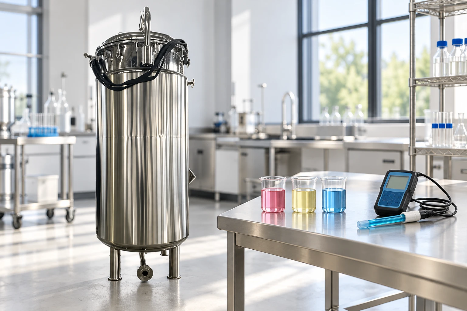
The tracer should be detectable, compatible, safe, and small enough not to change density or viscosity significantly. Conductivity is convenient for many water-based trials, but it may not represent viscous or multiphase products. A pH tracer can change chemistry. Dye offers visual evidence but may be hard to quantify. Calibrate instruments in the test fluid and understand resolution, drift, and response lag.
Place feed and sensors deliberately
A sensor close to the addition point may report completion long before the rest of the vessel. Use multiple locations or move samples according to a defined plan. Include top, bottom, near-wall, and outlet locations when they represent process risk. The feed point, addition duration, and initial mixing condition must be consistent. An instantaneous mathematical step is rarely achieved by a real pump or manual addition.
Calculate the normalized response
A common analysis converts each reading to a normalized response using its initial value, final stable value, and value at time t. Mixing time is then the earliest time after which the response remains within the chosen band. Apply the same calculation to each sensor and use the slowest required location. State how the final value was determined and how noise or sensor lag was treated.

Separate circulation from sensor behavior
A long tail may represent a genuine poorly exchanged region, slow dissolution of the tracer, sampling-line holdup, or sensor response. Run a calibration step and inspect the sampling path. A recirculation sample taken from one nozzle measures the material reaching that nozzle, not necessarily the complete tank. Use physical understanding and replicate tests before changing hardware.
Test the operating envelope
Repeat at minimum, normal, and maximum working volume; at relevant viscosity and temperature; and at planned speeds. Low liquid level can expose the impeller or create a vortex. High viscosity can weaken circulation. Ingredient order can create density layers. Include a realistic startup condition and test after any change to impeller, baffles, feed location, tank internals, or control sequence.
Scale up with the right constraint
Geometric similarity is useful but seldom complete. Constant rpm changes tip speed with impeller diameter. Constant tip speed changes rotational speed. Constant power per volume and constant circulation time impose other relationships. Select the scale-up basis from product and process limits, then verify at plant scale. Treat pilot mixing time as evidence, not a guaranteed production result.
Use results in the batch procedure
Set routine mixing time with a justified allowance above demonstrated performance, while avoiding needless shear, foaming, energy, or cycle delay. Define when timing starts, required speed, addition completion, temperature range, and what happens after an interruption. Trend batch data so increasing time or unstable measurements trigger inspection of the impeller, baffles, viscosity, sensor, or recipe execution.
Warning signs and troubleshooting boundaries
Important warning signs include different endpoints at different sample points, a long response tail, oscillating readings, a fast sensor near the feed point but slow remote samples, or blend time that changes sharply with liquid level. Stop and place the equipment in a safe condition when continued operation could damage the product, equipment, environment, or people. Diagnose from observations and records before changing several variables at once. A general article cannot authorize work on energized, pressurized, hot, corrosive, rotating, vacuum, or contaminated equipment.
Commissioning plan
Before startup, compare the installed equipment with the approved drawing and material list. Confirm orientation, fasteners, supports, guards, connections, instrument ranges, control direction, alarms, interlocks, drainage, access, and utilities. Start with a controlled mechanical check, then use a representative process condition. Record baseline speed, load, pressure, temperature, vibration, time, and the acceptance result relevant to blending tank mixing time calculation. Investigate deviations rather than normalizing them.
Maintenance and change control
Set inspection tasks from risk, service severity, manufacturer instructions, and observed condition. Keep critical spare parts identified by controlled material and drawing reference. Review changes to product, concentration, temperature, batch size, speed, cleaning, seals, software, piping, or operating sequence because they can invalidate the original basis. After maintenance, verify assembly, containment, direction, controls, and performance before full production.
Information to send with an RFQ
Provide the process description, product or chemical identity, properties across the operating range, tank geometry and levels, required duty, utilities, control philosophy, cleaning method, site environment, hazards, documentation, and acceptance test. Ask the supplier to return a completed data sheet, dimensioned drawing, material list, performance basis, motor and mechanical information where applicable, deviations, exclusions, maintenance access, spare parts, and test proposal. For blending tank mixing time calculation, the quotation should make the design assumptions visible enough for technical comparison.
Authoritative references
Use the sources for their stated scope. Standards, law, chemical guidance, and manufacturer instructions specified by the project take precedence over this overview.
Educational video
The following video from LearnChemE, University of Colorado Boulder supports the underlying engineering or safety concept. It is supplementary and is not a YIYI product claim.

Open Blending Process: Dynamic Modeling on YouTube.
Related YIYI equipment and guides
Review the related YIYI equipment page and the primary topic guide. Complementary reading includes blending tank versus mixing tank, batch mixing tank cycle time, mixing vessel specification guide. Each page answers a separate part of the purchasing or operating decision.
Frequently asked questions
What information is essential for blending tank mixing time calculation?
Start with the actual duty, operating range, material or product properties, tank geometry, hazards, cleaning method, utilities, and a measurable acceptance result. Do not select from volume or a product name alone.
Can one rule or ratio be used for every tank?
No. Rules of thumb are screening tools. Geometry, fluid behavior, internals, operating level, process risk, and scale change the result. Confirm the final design through calculations, supplier evidence, and representative testing.
What should be checked after installation?
Compare the installation with approved drawings, verify materials and connections, test controls and safeguards, run a controlled representative trial, and record a baseline for future maintenance and troubleshooting.