

Heat exchanger cross contamination detection combines process evidence, representative sampling, and an approved integrity investigation to determine whether fluid has passed between circuits. An unexpected conductivity, composition, microbial result, pressure change, or product-quality deviation can be a warning, but none automatically proves a leaking exchanger. First protect the process and retain evidence, then distinguish an internal leak from valve errors, sampling contamination, upstream changes, and other sources. Do not restart solely because one pressure test or one sample is acceptable. The release decision must address the actual contamination risk and the conditions that existed during operation.
Understand the possible leak path
In a conventional exchanger, a wall separates the two fluids. A damaged tube, plate, joint, or other boundary can permit transfer if the pressure difference drives it. The direction can change during startup, shutdown, pressure loss, or cleaning. A normal operating pressure relationship does not describe every transient or every isolated section.
The US Food and Drug Administration’s heat exchanger contamination guidance explains why circuit pressure and leakage matter in sensitive applications. Its discussion should be applied within the actual process and current requirements. The existing double-tubesheet exchanger guide addresses a design approach; this article focuses on investigating a suspected event in operating equipment.
Stabilize the process and preserve evidence
Follow the plant’s response procedure for a suspected contamination event. Identify affected material, stop or isolate equipment as required, and prevent unreviewed product release. Preserve process trends, alarms, valve positions, cleaning records, sample results, and recent maintenance information. A well-intentioned flush can remove evidence if it begins before the investigation team has assessed what must be retained.
Record when the first abnormal result appeared and the last known acceptable condition. Include production batch boundaries and operating changes. The affected period may not begin at the alarm time if the measurement is delayed or samples are tested later. Define the scope with quality and engineering personnel rather than choosing an arbitrary number of preceding batches.
Build a differential diagnosis
A conductivity rise can indicate utility ingress, but it can also reflect a formulation change, sensor drift, temperature compensation, or residue in a sample point. A microbial result can originate from sampling technique or another part of the process. A change in tank level can arise from a valve route rather than an exchanger breach. List plausible alternatives and the evidence needed to separate them.
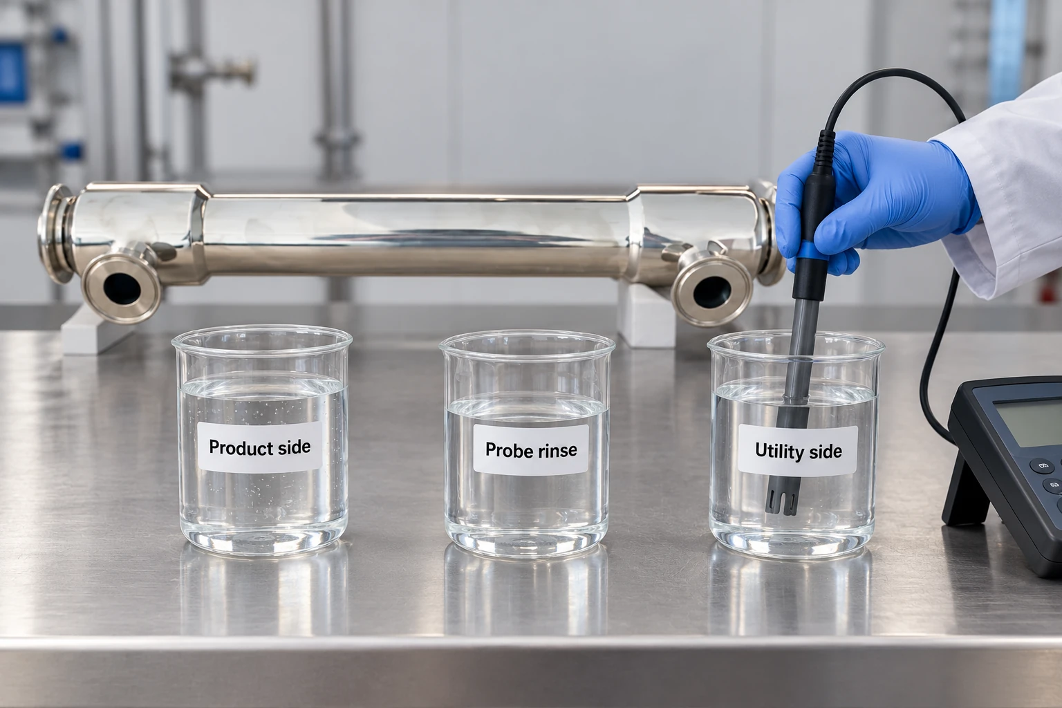
Use more than one independent line of evidence where the consequence warrants it. Compare both circuits, upstream and downstream samples, and relevant blanks. Ensure the analytical method can detect the substance at the concentration of concern. A test that cannot distinguish the two fluids cannot provide useful proof of crossover.
Use thermal-performance monitoring and measurement checks to investigate changing duty, while assessing composition and integrity separately. A thermal trend alone does not prove crossover.
Choose indicators that fit the two fluids
An appropriate marker depends on the actual chemistry and acceptable contamination threshold. Conductivity may help where the circuits differ sufficiently in ionic content. Other cases can require a specific chemical assay, organic-carbon measurement, microbiological investigation, or a validated tracer method. The method must be compatible with the equipment and the eventual cleaning and release requirements.
Do not introduce an unapproved tracer into a production circuit. Review its safety, compatibility, detectability, background level, and removal method. If a surrogate is used for a test, state what it represents. The absence of a detectable marker is meaningful only within the sampling coverage and detection capability of the method.
| Evidence source | Question it can help answer | Limitation to document |
|---|---|---|
| Circuit pressure trends | Could fluid have crossed in the observed direction? | Missing transients or remote measurement locations |
| Paired samples | Does the downstream composition differ from upstream? | Sampling contamination and analytical uncertainty |
| Utility chemistry | Is there a plausible marker for ingress? | Similar composition can make a marker uninformative |
| Integrity test | Is a defect detectable under the test conditions? | Conditions can differ from hot operating service |
| Maintenance history | Was a boundary opened, repaired or stressed? | A clean history does not prove present integrity |
| Valve and piping review | Could another route explain the result? | Drawings must match the installed configuration |
These are investigative categories rather than prescribed tests. Agree a method with competent personnel and the relevant equipment and process requirements. Measurement traceability and calibration are supported by the NIST calibration resources.
Review pressure differences over the whole cycle
Compare pressures at relevant locations and times, accounting for elevation and flow losses where material. A gauge near a pump can differ from pressure at the exchanger boundary. Review loss of utility supply, product pump stops, thermal expansion in trapped sections, and cleaning modes. A favorable pressure difference during stable production does not rule out crossover during a shutdown transient.
Identify whether the process deliberately maintains one circuit at a higher pressure as part of its contamination-control strategy. Verify that the strategy actually applied during the suspect period and remains appropriate for the product. Pressure control can reduce a particular direction of contamination but does not repair a damaged boundary or prove that no product entered the utility system.
Plan integrity testing around the suspected defect
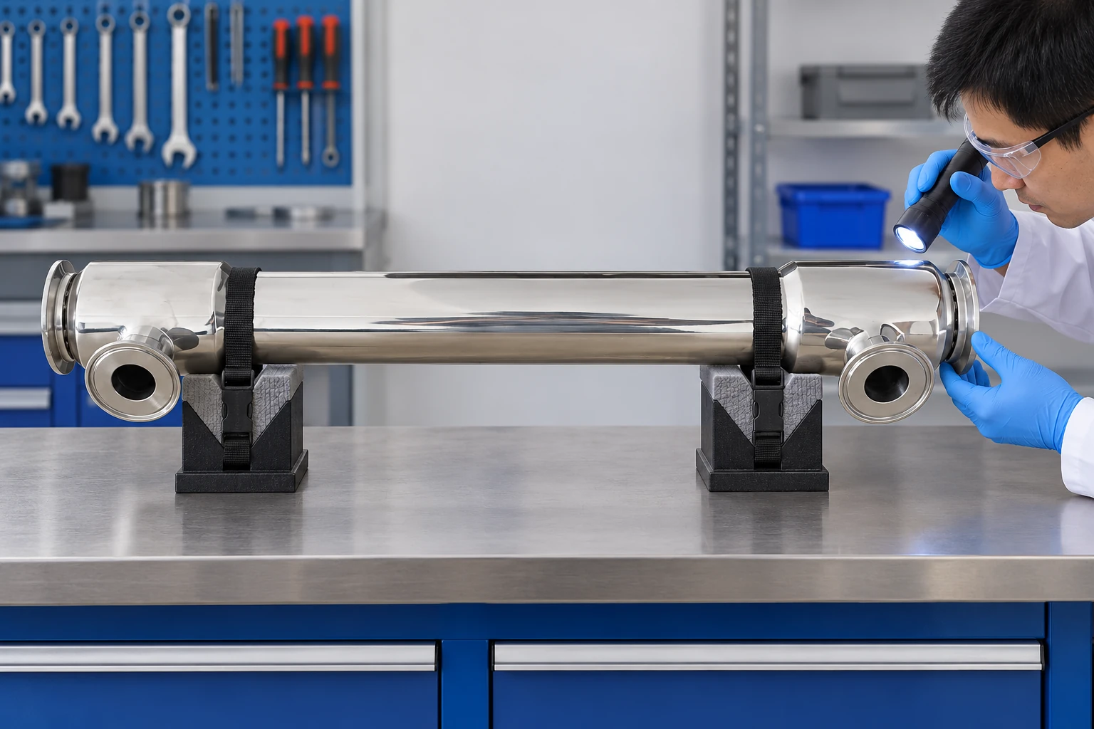
Select a test suitable for the construction, material, defect mechanism, and required sensitivity. Review the manufacturer’s instructions and the permitted test conditions. A pressure test, tracer test, visual inspection, or another non-destructive method may be appropriate, but each has a defined scope. Do not apply a generic test pressure to an exchanger without verifying the allowable differential and component limits.
Prepare the equipment safely. Isolate pressure, temperature, chemicals, and connected equipment, and manage stored energy. The HSE pressure-systems resources provide general context for pressure-system safety where applicable. A test procedure must include personnel protection and a controlled return to service, not merely an acceptance number.
Interpret a negative test cautiously
Some defects depend on temperature, differential expansion, vibration, or a particular pressure direction. A room-temperature test may not reproduce them. Conversely, an abnormal test result can arise from an external fitting or test rig rather than the process boundary being investigated. Record the configuration and locate the leak path before attributing the result to a specific component.
State the detection limit and the actual exposure time. A negative result means no leak was detected by that method under those conditions. It does not establish an unlimited zero-leak claim. If the operating evidence remains inconsistent with the test result, investigate the discrepancy before release rather than selecting whichever result is more convenient.
Connect the finding to the damage mechanism
If a leak is confirmed, determine whether corrosion, erosion, fatigue, thermal stress, vibration, manufacturing damage, or maintenance work contributed. Replacing one damaged part without addressing the mechanism can lead to recurrence. Review the operating envelope and whether the equipment still suits the fluids and cleaning regime.
The tube material selection guide addresses compatibility inputs, while thermal expansion design covers movement and stress considerations. These related topics support a cause investigation; they do not identify the cause from a contamination symptom alone.
Define evidence for repair and restart
After repair, verify the repair documentation, applicable inspection or testing, cleaning, and the condition of both circuits. Determine whether utility piping or downstream equipment was also contaminated. A successful exchanger test alone does not release affected product or confirm that the wider system is clean. Use the site’s quality and safety decision process.
For a double-tubesheet heat exchanger, ask how the proposed construction exposes leakage, how the intermediate region is monitored or drained, and what conditions can obscure an indication. Do not infer an independently monitored leak chamber from a product photograph. Specify the evidence required for the actual assembly and duty.
Include the sample containers and handling conditions in the investigation plan. A clean analytical instrument cannot correct a contaminated sampling valve or a container unsuitable for the analyte. Record blanks, hold times, transport conditions, and chain of identification where relevant. This makes it possible to distinguish a real process signal from a sampling artifact before a repair decision is made.
Keep a usable investigation record
Retain the event timeline, sample plan and results, circuit conditions, test method, detection limits, identified defect, repair evidence, and restart approval. Record remaining uncertainties and the monitoring needed after return to service. The next review should be able to explain why the equipment was released and which operating changes would require another assessment.
Further learning: exchanger behavior
The following educational simulation explains heat exchanger operation. It helps place flow and temperature observations in context, while contamination detection requires the specific evidence described above.
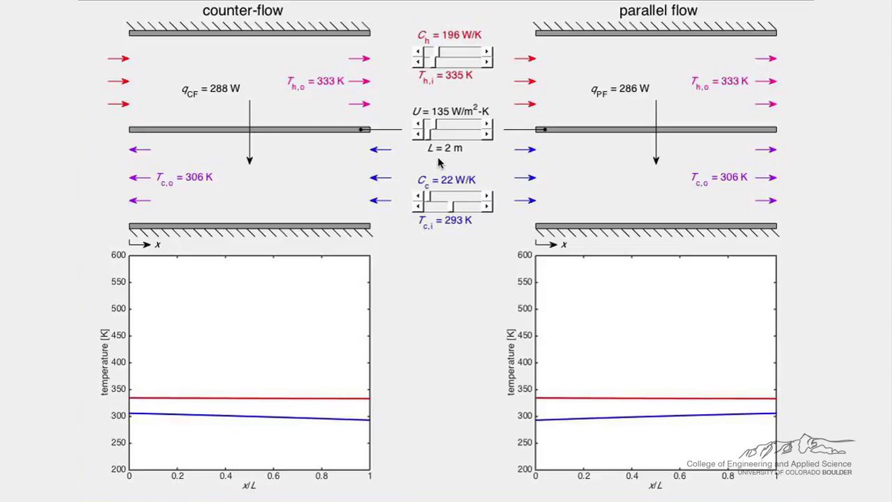
Watch Heat Exchanger (Simulation) by LearnChemE
FAQ
Does higher product pressure guarantee no contamination?
No. Pressure relationships can change during transients and shutdowns, and the strategy does not prove boundary integrity. Review the complete operating cycle and the possible transfer directions.
Can conductivity alone prove an internal leak?
Not in every process. It requires a meaningful difference between fluids, suitable sampling, and consideration of other causes. Confirm important findings with appropriate independent evidence.
Is one successful pressure test enough to restart?
Only if the approved investigation and release requirements are satisfied. Test conditions, detection capability, cleaning, affected product, and unresolved operating evidence must all be considered.


