

Heat exchanger thermal expansion must be assessed from the different temperature histories of the shell, tubes, tubesheets, supports, and connected piping. A fixed-tubesheet unit can be suitable when its calculated stresses remain acceptable. U-tubes, floating heads, or a properly designed shell expansion joint provide different ways to accommodate movement, with different cleaning and maintenance consequences. Choose the arrangement from the complete operating envelope rather than a single inlet-temperature difference. This guide explains how buyers can prepare that envelope, interpret a preliminary expansion estimate, and request evidence before approving equipment.
Identify what is expanding and what restrains it
A heated metal component tends to increase in length. If it can move freely, the main result is displacement. If other parts prevent that movement, mechanical loads develop. In a shell-and-tube exchanger, tubes and shell are connected through the tubesheets, and their average metal temperatures may differ considerably. They can also have different materials. The mechanical design must reconcile their attempted movements and the flexibility of the assembled equipment.
The process-fluid temperature is an input to this assessment, not automatically the temperature of every metal component. A wall separates two fluids and transfers heat between them. Temperatures also vary along the exchanger and during startup. A proposal based only on maximum hot inlet temperature can miss a more demanding combination, such as a cold shell during rapid tube-side heating. Conversely, a large inlet difference does not alone prove that a particular construction is unacceptable.
The British Stainless Steel Association thermal-property resources help identify suitable material data. Obtain the applicable coefficient over the temperature range being assessed. Do not substitute a familiar room-temperature value without checking its basis and units.
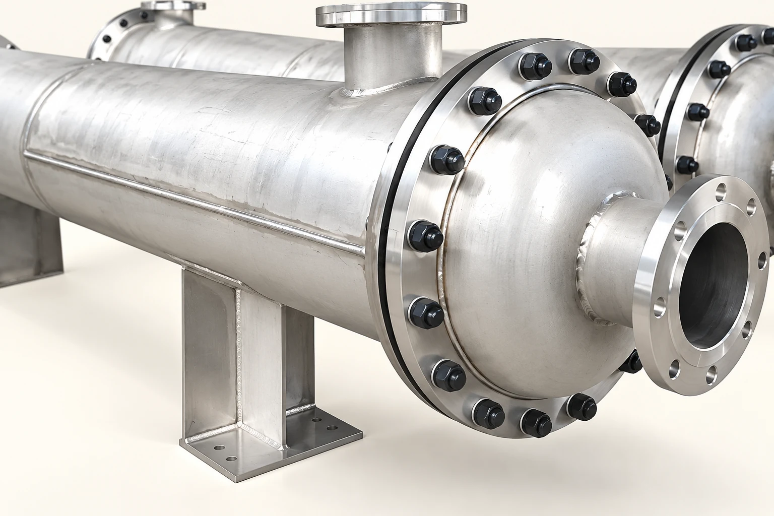
Build a temperature-case sheet before selecting a construction
Start with normal operation, minimum and maximum throughput, startup, shutdown, cleaning, and credible upset cases defined by the process team. For each case record both streams, expected duration, ramp rate, pressure conditions, and whether either side can remain isolated. A cleaning cycle can impose a very different temperature sequence from production. A steam-heated exchanger may see condensation and rapid local heating while the product side remains relatively cold.
Ask who controls each transition. A manually opened utility valve and an automatically limited ramp are different operating assumptions. State the measurements used to demonstrate the ramp, and identify the response to loss of product circulation. If the design relies on circulation before heating, that requirement belongs in operating instructions and interlocks where appropriate. It should not remain an undocumented calculation assumption.
Include the reference temperature used for fabrication and assembly, ambient conditions, and any hot installation condition. Give the supplier the fluid composition and required materials as well as temperatures. Changing the alloy changes expansion behavior, and the approved mechanical assessment should correspond to the actual material schedule.
Use free expansion as a screening calculation
For an approximately uniform temperature change, an illustrative free-length estimate is:
ΔL = α × L × ΔT
Here ΔL is the length change in metres, α is the linear expansion coefficient in 1/K, L is the initial length in metres, and ΔT is the temperature rise in kelvin. A temperature difference has the same numerical magnitude in kelvin and degrees Celsius. If α varies substantially over the range, use an appropriate integrated or mean value rather than treating it as constant.
For a purely hypothetical four-metre component with α = 16 × 10⁻⁶/K and a 100 K rise, free expansion is 0.0064 m, or 6.4 mm. A second four-metre component with α = 12 × 10⁻⁶/K and a 40 K rise would expand 1.92 mm. The difference is 4.48 mm. These assumed coefficients illustrate unit handling; they do not identify the alloy, allowable movement, or specification of a Kanger product.
This difference is not the displacement that every joint will experience, and it is not a stress calculation. Tubesheets bend, tubes and shell resist loads, supports interact with the foundation, and piping adds restraint. Mechanical analysis must consider the assembled stiffness and relevant pressure loads. The DOE heat-transfer handbook provides background on temperature fields and heat transfer; it does not replace the exchanger pressure-equipment design calculation.
Compare construction options through service requirements
The following comparison is a decision aid, not a statement that one arrangement always needs or never needs an expansion joint. Actual acceptability depends on the approved design, materials, temperature cases, and applicable equipment rules.
| Construction | How movement is considered | Questions that affect the purchase |
|---|---|---|
| Fixed tubesheet | Tubes, shell, and tubesheets share differential-expansion loads | Have all temperature cases been evaluated? Can shell-side deposits be managed without bundle removal? |
| Fixed tubesheet with shell expansion joint | A designed flexible shell element accommodates specified movement | What pressure, temperature, cycle life, corrosion conditions, and inspection access govern the joint? |
| U-tube | Tube geometry allows the legs to accommodate differential expansion | Can the bends and individual tubes be inspected and cleaned adequately for this service? |
| Floating head | One end of the tube bundle can move relative to the shell | What seals, pull space, maintenance access, and contamination risks need review? |
A shell expansion joint is a pressure-containing component. Selecting one is not equivalent to adding a flexible connector to a utility pipe. Its pressure rating, movement range, fatigue assessment, anchoring requirements where applicable, material compatibility, and inspection plan must be established by the responsible designer. Never retrofit a bellows based only on the free-expansion example above.
For the serviceability tradeoffs, read the separate fixed tubesheet versus floating-head guide. The Kanger fixed-tubesheet product page provides a starting equipment reference; the purchase order must still define the supplied construction and approved operating envelope.
Separate tube bending from external sanitary return bends
A visible U-shaped return in a sanitary multipass exchanger is not evidence that the equipment uses a conventional U-tube bundle. External return connections route process flow between passes. A conventional U-tube bundle has its own internal construction and mechanical behavior. Confirm the sectional drawing instead of assigning a construction type from the exterior photograph.
Similarly, a fixed-tubesheet photograph does not disclose allowable temperature difference or prove the presence of a shell expansion joint. Marketing images illustrate visible equipment only. Ask for a general arrangement, sectional drawing, material schedule, and calculation summary tied to the offered unit. If a requested feature is not shown clearly, resolve it before approving fabrication.
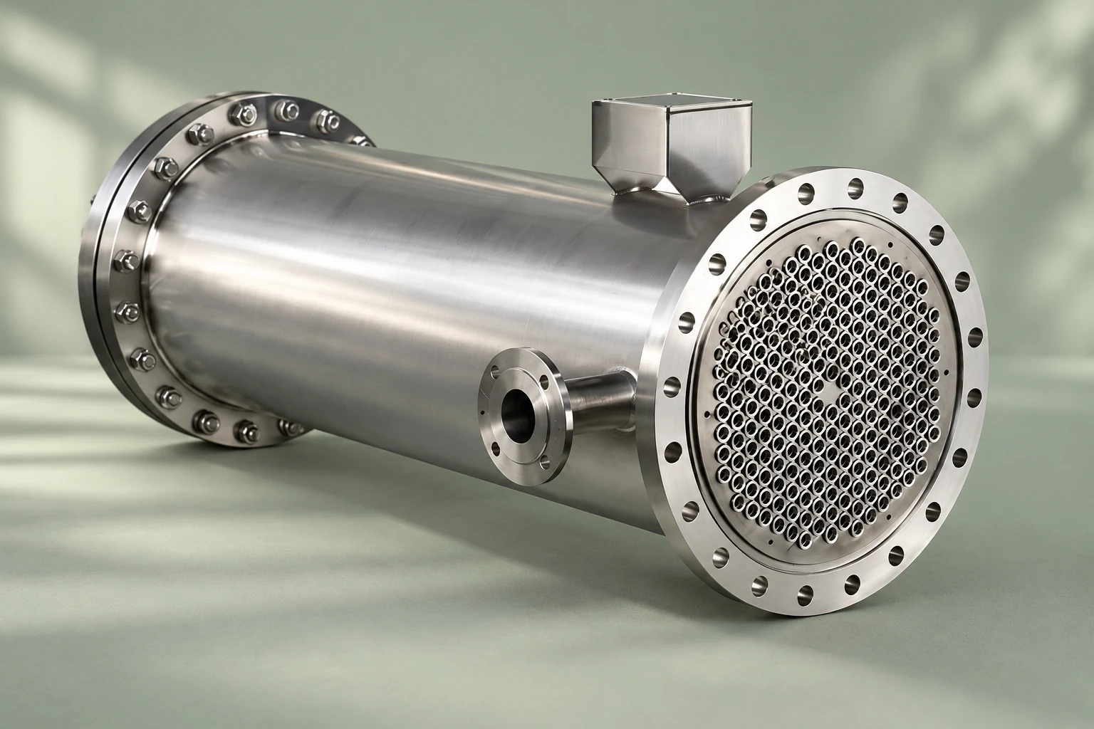
Review supports and connected piping together
Even when internal shell-to-tube stresses are acceptable, external equipment movement still matters. Supports must carry weight and operational loads while behaving as assumed by the mechanical design. The installation drawing should identify the intended restraint and movement at each support. Do not loosen bolts, enlarge holes, or add improvised sliding surfaces as an installation adjustment.
Connected piping can impose nozzle forces and moments, especially if thermal growth has no suitable accommodation. Ask the piping team to assess the hot and cold positions of the exchanger and adjacent system. Include valves, strainers, flexible elements, and nearby anchors. Installation should not force a misaligned pipe onto a nozzle and then treat the resulting load as normal.
An accessible support is easier to inspect after the first operating cycle. Provide room to observe intended movement and maintain approved fasteners. A support hidden behind a drain line or tightly boxed into a platform may make verification difficult even though the initial layout looks compact.
Evaluate repeated cycles and rapid transitions
A maximum-temperature case and a cycle assessment answer different questions. Equipment can encounter many heating and cooling cycles below its maximum temperature. Identify expected cycle frequency, cleaning schedules, batch operation, and irregular startup events. Where fatigue assessment is required, the supplier needs a realistic cycle definition rather than an arbitrary daily count.
Rapid thermal changes can produce local gradients before the whole component approaches a steady temperature. Explain credible sequencing mistakes and the safeguards used to prevent them. A startup procedure should state circulation, valve sequence, ramp requirements, venting, and the response to an unexpected temperature excursion. Avoid inventing a universal safe ramp rate: it depends on construction, materials, duty, and the validated design.
The commissioning checklist covers the wider handover process. Keep thermal-transition acceptance separate from a pressure test. Passing a pressure test alone does not demonstrate acceptable differential expansion throughout service.
Request a reviewable supplier package
Ask for the design basis, temperature and pressure cases, material properties, assessment method, relevant assumptions, and the proposed accommodation of movement. The package should identify which component or case controls the decision. It should also state the operating restrictions that follow from the assessment and where those restrictions appear in the final documents.
Connect the calculation to maintainability. If shell-side fouling is expected, verify how cleaning will occur. If an expansion joint is proposed, confirm access and inspection responsibilities. If a removable bundle is selected, reserve pull space and handling capacity. Compare whole-service costs rather than evaluating the initial equipment quotation in isolation.
Use the bundle-maintenance guide to prepare access questions. Submit fluid properties, temperature sequences, pressures, materials, installation drawings, and intended cycle frequency with your enquiry. A supplier can then explain an appropriate arrangement without guessing the operating case.
Further learning: temperature-driven movement
The following Practical Engineering explanation illustrates free and restrained thermal movement using civil structures. It is background physics, not a pressure-vessel construction or exchanger-sizing procedure. Apply the principle through the unit-specific mechanical assessment described above.

Watch Why Bridges Move… by Practical Engineering
Frequently asked questions
Does every fixed-tubesheet exchanger need a shell expansion joint?
No. The need depends on calculated stresses and the applicable design cases. Materials, metal temperatures, geometry, pressure, tubesheet flexibility, and cycling all matter. A supplier must demonstrate the proposed construction rather than apply a universal temperature-difference rule.
Can free-expansion length determine the required bellows?
No. It is a preliminary movement estimate. A pressure-containing expansion joint also needs assessment of pressure, temperature, loads, movement, cycle life, corrosion, and installation restraint under the applicable design requirements.
Is an external sanitary U-return the same as a U-tube bundle?
No. The exterior return routes flow between passes. Confirm the internal construction from an approved sectional drawing before treating it as a conventional U-tube bundle or assigning its expansion behavior.
What information should a buyer send first?
Send both fluid temperature histories, pressures, composition, materials, expected cycles, cleaning conditions, and the installation arrangement. Include startup and shutdown sequences so the assessment covers the actual service envelope.


