

A double tubesheet heat exchanger uses separated tube sheets to create an observable leakage path at the tube-to-tubesheet joints. This can help reduce cross-contamination risk where product and utility fluids must remain separate. It does not make the entire exchanger leak-proof: tube-wall damage, blocked leakage passages, unsuitable materials, and operating errors still need controls. Buyers should specify the separation arrangement, leakage discharge route, inspection access, operating pressures, and response to an alarm before comparing prices. A product name or polished exterior alone cannot confirm how the internal barriers work.
Identify the contamination route before choosing a design
Start with a process sketch showing the product stream, heating or cooling utility, connected equipment, and discharge destinations. Mark where contamination would affect product quality, operator safety, downstream equipment, or a batch-release decision. Include startup, cleaning, shutdown, and idle periods. A utility that is harmless during normal production may introduce an unacceptable residue during a cleaning changeover.
Distinguish joint leakage from tube-wall leakage. A separated tubesheet arrangement addresses leakage around tube-end joints by providing an intermediate route that can be observed or monitored. A through-wall defect along a tube is a different path. The specification therefore needs an integrity-testing strategy for the full heat-transfer boundary, rather than relying on one construction feature.
Record which stream is more sensitive and what contamination would be detectable. Conductivity, colour, or a visible drip may not reveal every relevant contaminant. Ask the process owner to define the required detection method and the action threshold. An exchanger supplier can explain equipment construction; the owner must connect that construction to the site’s product-quality requirements.
Understand what the separated tube sheets actually do
In an appropriate design, adjacent tube sheets are separated, with a space that provides an outward route for joint leakage. The important question is where fluid travels after a joint fails. Request a sectional drawing that identifies the product-side joint, utility-side joint, intervening space, and drainage or monitoring connection. Follow that route on the drawing without assuming that every visible external port is a leak outlet.
The FDA’s historical Heat Exchangers to Avoid Contamination explains the contamination concern and the purpose of an observable gap. It also warns that enclosed leakage spaces need discharge openings that remain clear. This older inspection guide provides engineering context; its discussion of proposed rules is not a statement of current requirements for every facility.
Compare that description with the proposed manufacturer’s drawing. A double-pipe exchanger, a double-wall tube, a multipass exchanger, and a double-tubesheet exchanger describe different features. None of those names establishes equivalent performance under a particular failure. Have the supplier state which leak paths its proposed arrangement addresses and which remain outside its protection.
Specify the leakage space and its discharge destination
Define whether leakage is visible directly, collected through a drain, or detected by an instrument. The route must remain accessible after installation, including after insulation, guarding, and adjacent piping are fitted. A drain hidden behind a frame or terminating inside an enclosed cabinet is difficult to inspect during routine rounds.
Consider the discharge itself. A leaking hot utility, corrosive fluid, or cleaning solution may create a secondary hazard. The collection arrangement should let personnel detect leakage while avoiding exposure and without defeating the intended separation. Any enclosure, vent, or connection needs engineering review so that it does not unintentionally pressurize the intermediate space.
For a collected discharge, request a drawing of the complete route to the collection point. Establish who checks it, how often it is checked, and what constitutes an abnormal condition. If instruments are proposed, define their wetted materials, range, cleanability, test method, and failure indication. A monitoring port without an operating procedure is an unfinished control.
Review pressure behaviour in every operating state
Prepare a pressure matrix for normal production, startup, cleaning, shutdown, and utility failure. Include the conditions that occur when one stream stops flowing while the other remains pressurized. State where each pressure is measured and whether the recorded values include static head. Comparing readings at different elevations can hide the true pressure difference across the exchanger.
The FDA’s historical High Purity Water System inspection guide discusses positive pressure and double-tubesheet construction as approaches to contamination control. That discussion should inform a project risk review rather than become an unsupported claim that a named design automatically meets today’s application-specific requirements.
Do not infer a safe pressure hierarchy from normal inlet readings alone. Loss of a product pump, valve closure, trapped liquid heating, and cleaning connections can change the conditions. Ask for the allowable pressure on each side and any restrictions on simultaneous or separate-side operation. Protective devices and isolation procedures must follow the approved system design.
Turn the concept into an inspection checklist
The following table is a proposed purchasing and acceptance checklist. It organizes evidence to request; it does not set universal pressure-test values or regulatory limits. The cited FDA guides explain the leakage concerns, while the final criteria must be agreed for the actual service and governing requirements.
| Review item | Evidence to request | Practical acceptance question |
|---|---|---|
| Barrier arrangement | Section drawing and joint details | Can both fluid boundaries and the intermediate route be followed clearly? |
| Leak discharge | Drain or open-gap layout | Is the discharge observable, clear, and safely routed after installation? |
| Tube integrity | Approved examination and test procedure | Does the procedure address tube-wall defects as well as end joints? |
| Pressure conditions | Operating-state matrix | Are separate-side, startup, and failure conditions included? |
| Materials | Wetted-parts schedule and certificates | Are product, utility, and cleaning exposures all assessed? |
| Monitoring | Instrument and alarm documentation | Can an alarm be tested and linked to a defined response? |
| Service access | Installation drawing and removal space | Can inspectors reach the relevant joints and leakage route? |
During document review, assign an owner and evidence reference to each line. A drawing approval should not silently close a physical inspection item. Conversely, a photograph cannot replace a pressure-rating calculation. Keep open items visible until the responsible engineering or quality reviewer accepts the required evidence.
Check cleanability without hiding the separation feature
Trace cleaning solution through the product passage and identify any locations that can retain fluid. Confirm the intended installation orientation and ask whether changing that orientation changes drainage. Exterior sanitary connections do not by themselves demonstrate that every internal surface can be cleaned or drained as required.
Review the leakage space separately from the product cleaning circuit. Decide whether it is inspected, cleaned, or otherwise managed and how access is preserved. Avoid improvised caps, sealants, or insulation that conceal a discharge point. If the design requires a closure for a particular operating reason, the approved drawing should explain the function and how leakage remains detectable.
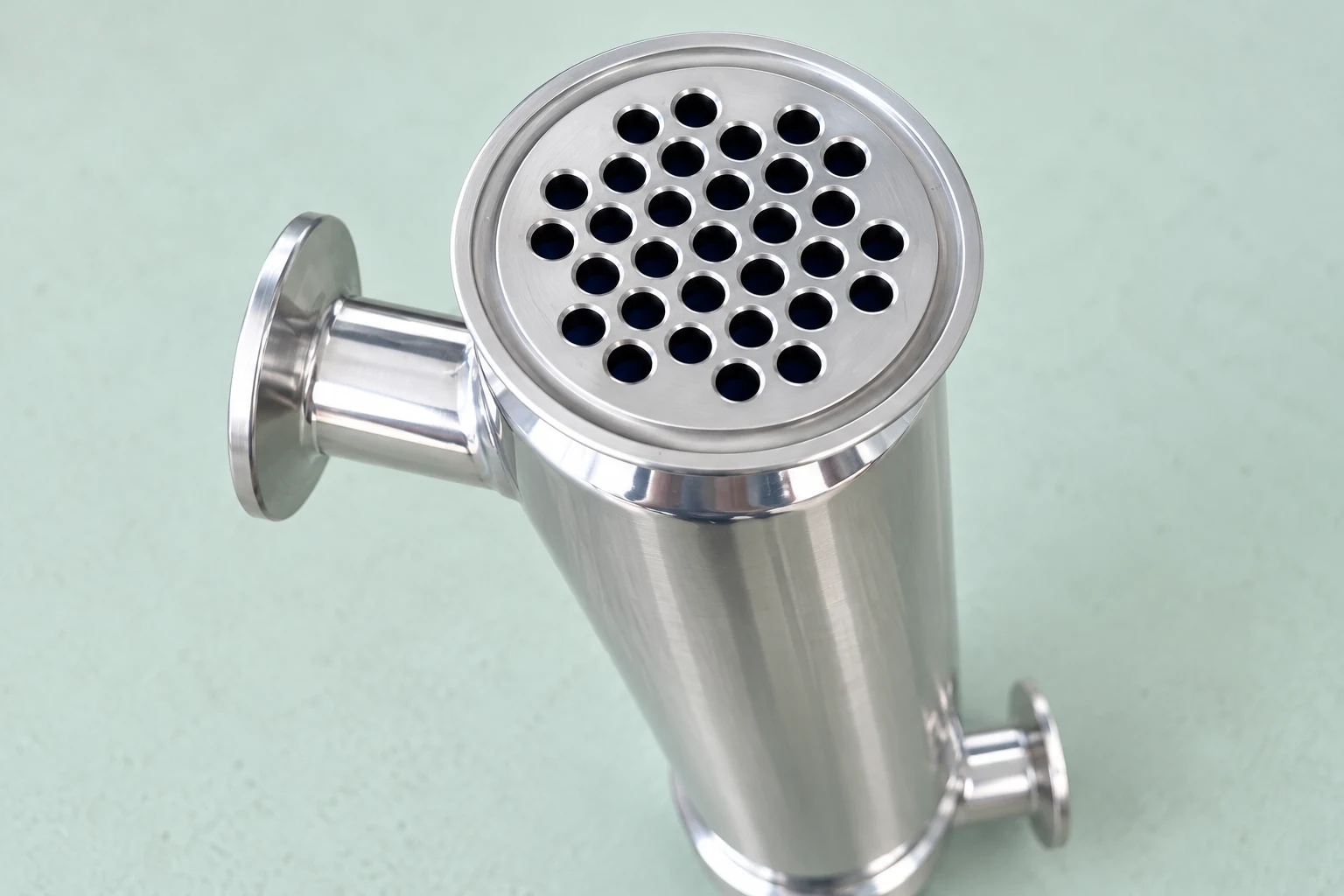
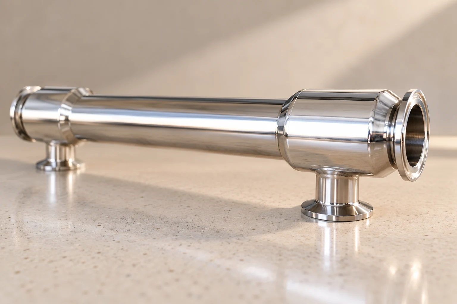
For a starting equipment discussion, review YIYI’s double tube sheet heat exchanger. Its published product photographs are useful references for exterior equipment and tube-end access. They do not establish the supplied internal gap dimensions, validated cleaning performance, material certificates, or suitability for a named pharmaceutical process. Request those documents for the proposed unit.
Plan factory and site checks around the failure paths
Before testing, agree the test boundaries, media, pressures, holding periods, examination method, and acceptance criteria under the applicable design requirements. The test plan should state which defects each step can reveal. Do not invent a single pressure or duration that is supposedly appropriate for all exchangers.
At the factory, compare the unit identification with the approved drawing and material schedule. Check that visible connections correspond to the documentation and that access provisions exist. Record the examination results and any repairs. A completed test sheet needs a clear unit reference, procedure reference, date, and responsible sign-off.
At the site, repeat the checks affected by transport and installation. Verify the leakage route remains open or connected as designed, instrumentation is functional, and operators can inspect the intended locations. Compare installed piping with the pressure matrix before introducing product. The heat exchanger commissioning checklist provides a separate framework for bringing the complete system into service.
Define the response to a detected leak
An alarm should trigger an approved sequence, not an improvised repair while production continues. Define safe isolation, product disposition, notification, investigation, and return-to-service authorization. Consider whether batches produced since the last satisfactory integrity check need review. The process owner’s quality system should determine that decision.
For maintenance planning, distinguish a clear leakage outlet from a confirmed intact tube bundle. Absence of a drip is not proof that all heat-transfer surfaces remain sound. Retain baseline test results and operating observations so later changes can be investigated against evidence. After repair, repeat the checks relevant to the original failure and any parts disturbed by the repair.
Use the broader shell-and-tube bundle maintenance guide to understand access arrangements. The shell-side versus tube-side allocation guide addresses stream placement. These decisions complement contamination control but do not replace its failure-path review.
Prepare a quotation package that suppliers can answer
Send the two fluid descriptions, full temperature and pressure envelopes, required duty, cleaning conditions, contamination consequences, installation orientation, and document requirements. Include the leakage-detection expectation and the site’s response procedure. Ask bidders to identify exclusions explicitly and attach drawings that show the proposed separation arrangement.
Compare proposals by evidence rather than by the phrase “double tubesheet.” If one supplier includes monitored collection and another supplies an exposed gap, assess each against the actual installation and operating practice. Resolve uncertain leak paths and test boundaries before purchase. This makes the equipment choice reviewable and prevents assumptions from reaching installation.
For a visual introduction to the two-stream heat-transfer principle, the following LearnChemE simulation is useful. It explains thermal operation; it is not a demonstration or validation of double-tubesheet leakage protection.
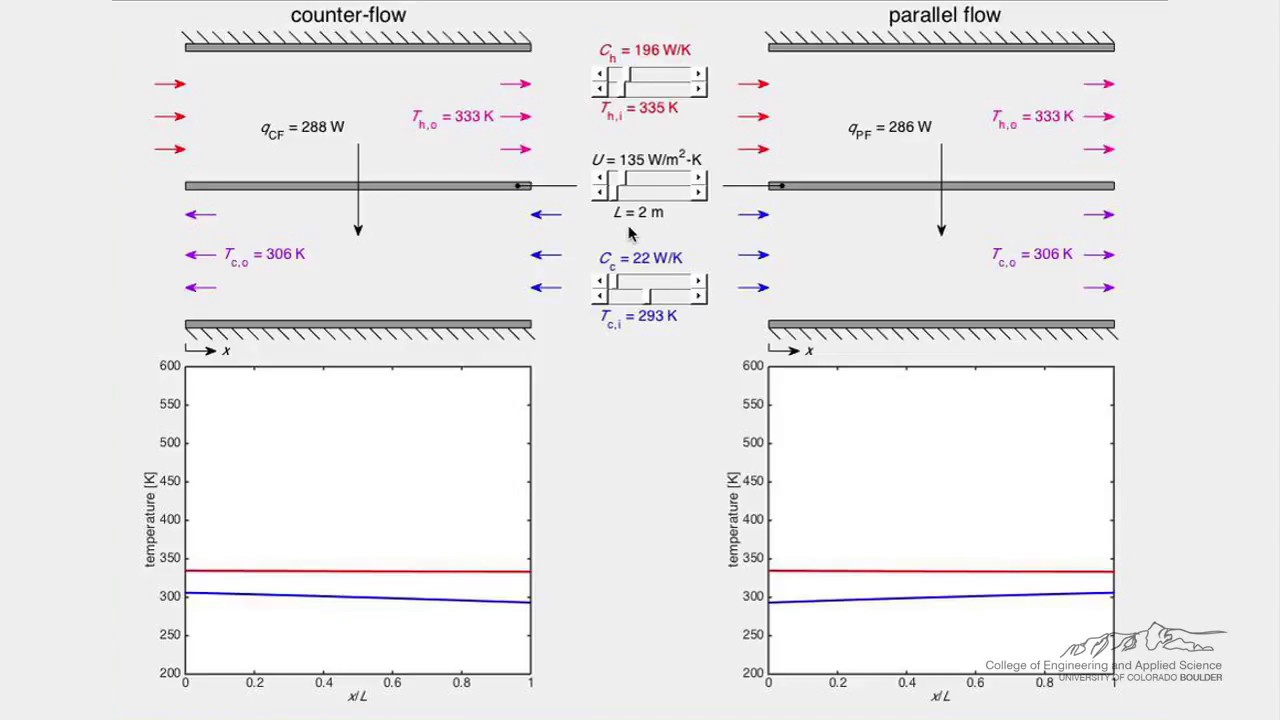
Watch Heat Exchanger (Simulation) by LearnChemE
Frequently asked questions
Does a double tubesheet exchanger prevent every possible leak?
No. An appropriate separated arrangement can provide an outward path for tube-end joint leakage. Tube-wall damage and other boundary failures still need integrity checks, compatible materials, and an operating response.
Can the exterior photograph prove the internal barrier arrangement?
No. Use the photograph to check equipment appearance and accessible connections. Confirm internal separation, leakage paths, and joint construction using approved sectional drawings and inspection records.
Should the leakage outlet be capped to keep the installation tidy?
Do not alter it without an approved design review. Blocking or concealing the intended route may stop leakage being observed or change pressure in the intermediate space. Follow the documented collection and discharge arrangement.
What should a buyer request first?
Request a sectional drawing showing both stream boundaries, the intermediate space, and the leak discharge route. Combine it with the operating pressure matrix, material schedule, and approved integrity-test plan before accepting a quotation.


