Fermenter pH control keeps culture conditions within an approved range by combining a representative pH measurement, adequate mixing and bounded acid or base addition. The control loop is only as reliable as the probe location, calibration, dosing-point design and response time. A buyer should specify the process range, expected acid/base demand, approved reagents, mixing conditions, sensor technology, sterilization method, addition limits and alarm strategy. The objective is not a perfectly flat trend; it is stable, traceable control without local concentration shocks, overdosing or hidden sensor error.
Why pH changes during fermentation
Cells consume substrates and generate acids, bases, carbon dioxide and other metabolites. Gas stripping, feed composition, temperature and buffer capacity also affect the reading. The direction and rate of change can differ by batch phase. Process development should define the acceptable band and expected demand; the equipment supplier should not invent biological setpoints.
Probe selection and placement
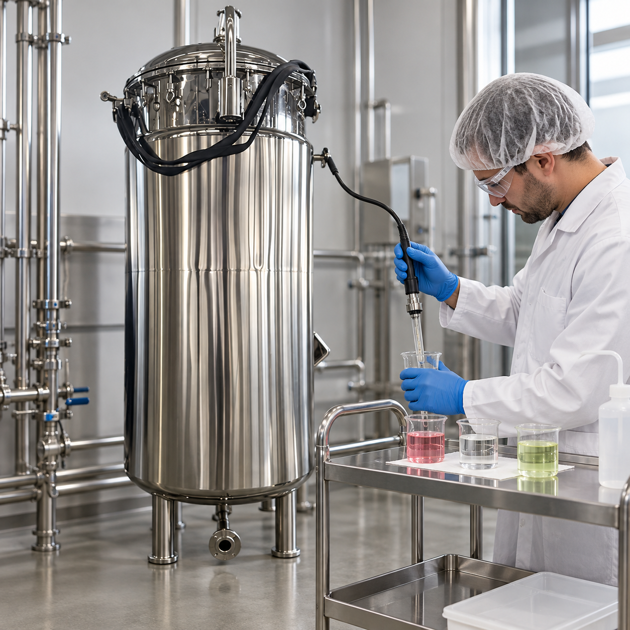
Select a sensor compatible with temperature, pressure, sterilization exposure, medium and required accuracy. Placement should expose the sensing element to representative, moving liquid while avoiding direct bubbles, a stagnant pocket, the immediate dosing jet or impeller damage. The port must support removal, inspection and maintenance without creating an uncleanable geometry.
Calibration practice depends on the sensor and process. Define buffers, temperature compensation, acceptance tolerance and what happens when pre- and post-batch checks disagree. A successful transmitter check does not prove the installed probe is representative. Compare the trend with additions and process events to identify drift or coating.
Dosing-point and mixing design
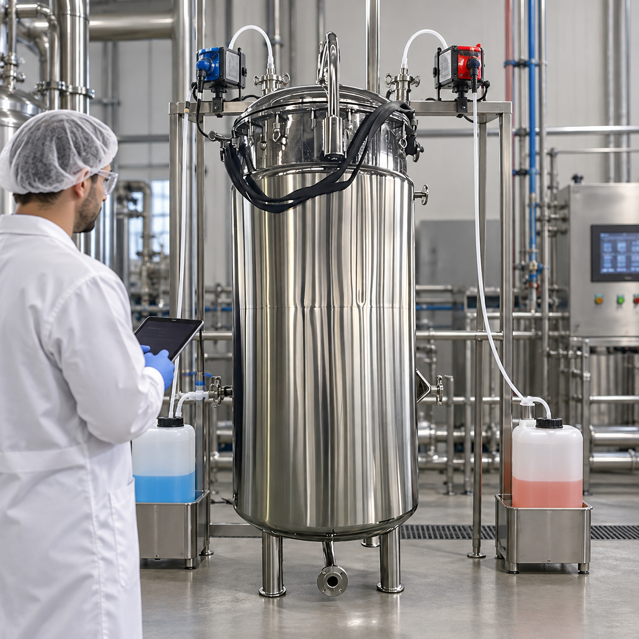
Introduce acid or base where circulation disperses it quickly, but do not aim the jet at the pH probe, seal or vessel wall. Concentrated reagent can create a local extreme before the bulk liquid responds. Review reagent compatibility, tubing, check valves, siphon protection, container connection and backflow prevention. The dosing assembly must fit the cleaning and sterilization boundary.
Pump capacity should cover peak demand while retaining useful resolution at normal demand. An oversized pump can deliver too much during one control pulse. Use minimum pulse, maximum rate, cumulative batch limit and a mixing delay before reassessment. If both acid and base are available, prevent simultaneous addition and excessive cycling.
| Item | Design question | Evidence |
|---|---|---|
| pH probe | Compatible with broth and sterilization? | Datasheet and calibration record |
| Location | Representative flow without bubbles or dosing jet? | Nozzle drawing and mixing review |
| Dosing pump | Range, resolution and fail state? | Delivery test across operating range |
| Reagent path | Backflow, siphon and contamination controlled? | Piping review and functional test |
| Logic | Limits, delays and alarms defined? | Loop challenge and batch trend |
Control tuning and troubleshooting
Control response includes sensor lag, mixing time, pump delivery and chemical reaction. Aggressive tuning can cause oscillation and alternating acid/base use. Start from a known mixing condition, use bounded output and tune with a representative liquid where possible. When pH drifts, check calibration, temperature compensation, coating, gas changes, feed composition, pump delivery and mixing before changing the setpoint.
Connections to the wider fermenter design
pH behavior can change with aeration and carbon-dioxide stripping, so review the fermenter airflow control guide and oxygen transfer guide. The fermenter operating overview provides the parent context. Use the Kanger fermenter product page when defining nozzles and controls.
Authoritative references
The NIST calibration resources support measurement terminology, the FDA PAT framework supports science-based measurement and control, and the NCBI biotechnology reference provides bioprocess context.
Build fermenter pH control into the equipment specification
Begin with the process objective, organism or product, working volume, batch phases and permitted operating range. State which values are process-development inputs and which are equipment limits. The inquiry should define utilities, cleaning, sterilization, instrumentation, automation boundary and documentation. A component name alone does not establish performance; the supplier needs the duty, expected range, installation constraints and acceptance method.
Review the entire operating sequence: preparation, filling, startup, cultivation, additions, harvest, cleaning, sterilization, cooling and storage. Identify credible failures and required responses. Measurements used for release or control need a defined calibration path. Valves and pumps need stated fail positions. Software alarms should correspond to an operator action, and the batch record should preserve setpoint, actual value, alarm, override and relevant process phase.
Factory and site acceptance
Factory tests can verify fabrication, instrument identity, wiring, valve action, software ranges and water operation. They do not automatically prove performance in process broth or under site utilities. Separate document review, factory testing and site testing. For each test, define the liquid, fill volume, temperature, pressure, utility conditions, stabilization time, instrument tolerance, raw data, calculation and pass criterion before testing begins.
At site, confirm gas, steam, water, electricity, drainage and exhaust capacity under realistic simultaneous demand. Repeat critical loop checks after installation because transport and reconnection can affect calibration, valve travel and piping resistance. Record deviations and closure evidence. Preserve approved drawings, instrument lists, calibration certificates, recipes, source files where applicable, test results and final settings in the equipment file.
Lifecycle review
Trend performance by batch phase instead of relying on a single endpoint. A gradual shift may reflect probe drift, fouling, filter loading, raw-material change or utility variation. Define who reviews trends, what triggers investigation and how maintenance effectiveness is confirmed. Changes to probes, pumps, spray devices, recipes, control logic or sterilization steps require review because they can alter validated performance.
After each campaign, compare the actual operating envelope with the design basis. Investigate recurring alarms, overrides and manual corrections. Check calibration, maintenance, procedure changes and utilities before changing a control setting. A concise deviation record should name the evidence, confirmed cause, corrective action, responsible owner and verification date. This makes fermenter pH control repeatable rather than a one-time commissioning demonstration.
Documentation and risk-review checklist
Translate each process requirement into an observable test. If the requirement concerns uniformity, define locations and timing. If it concerns measurement, define calibration and allowable error. If it concerns a valve, pump or final control element, define command, actual response, fail state and alarm. Avoid acceptance language such as “works correctly” because it does not state what will be measured or who decides whether the result passes.
Review the piping and instrumentation diagram against the delivered equipment. Confirm nozzle identity, flow direction, valve type, drain path, instrument range and access for maintenance. Trace each automated step from permissive through completion. An interlock should protect a named hazard or quality condition, while an alarm should lead to a defined operator response. Record intentional bypasses and prevent an undocumented override from becoming normal operation.
Plan tests around realistic boundary conditions
Test more than the easiest nominal point when the operating window is broad. Include low and high working volume, minimum and maximum utility conditions, and the process phase most likely to challenge control. Use a representative test medium when water would hide viscosity, buffering, foaming, drainage or heat-transfer effects. Where live-process testing is not practical, document the correlation and remaining uncertainty instead of presenting a surrogate test as complete proof.
Before testing, verify instrument calibration and synchronize timestamps. Record the recipe version, equipment configuration, utilities, temporary sensors and any manual action. Preserve raw trends rather than only screenshots. A summary should state the test condition, acceptance criterion, result, deviation and disposition. This makes later comparison possible when maintenance, a new recipe or a component replacement changes system behavior.
Prepare the operating team
Operators need more than a sequence of buttons. Training should explain why the control limit exists, which physical signs support the instrument reading, and when manual intervention is allowed. Provide inspection points that can be checked without defeating guards or opening the process. Procedures should cover startup, normal operation, alarm response, shutdown, cleaning, sterilization and return to service.
Maintenance planning should identify critical spares, wear parts, calibration tools and approved replacement specifications. A substitute probe, pump, valve or spray device can alter performance even when it fits the connection. Review replacements through change control, update drawings and repeat affected tests. Periodic review should use actual batch evidence to refine maintenance intervals without weakening approved limits.
Verify reagent delivery independently
Periodically measure actual pump delivery into a suitable receiver across the programmed range, using the approved reagent or a justified surrogate. Check suction condition, tubing condition, check valves and any pulsation or delay between command and delivery. Reconcile the measured volume with controller run time and batch totals. If the reagent concentration changes, update the process calculation and review pump resolution before use. This independent check helps separate a chemistry or buffering change from a mechanical delivery problem and gives the control engineer a reliable basis for tuning.
Educational video
This video provides additional background for the process principles discussed above. The written guide remains the controlling explanation.

Frequently asked questions
What should be defined before equipment selection?
Define the process duty, operating range, utilities, cleaning and sterilization boundary, instruments and acceptance test for fermenter pH control.
Can one component specification prove performance?
No. Performance depends on installation, vessel geometry, utilities, control logic and the documented test condition.
What records should be retained?
Keep approved drawings, calibration records, raw trends, test results, deviations, settings and maintenance evidence.