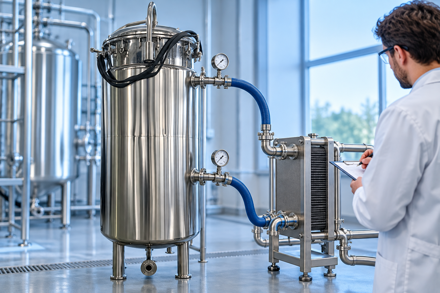
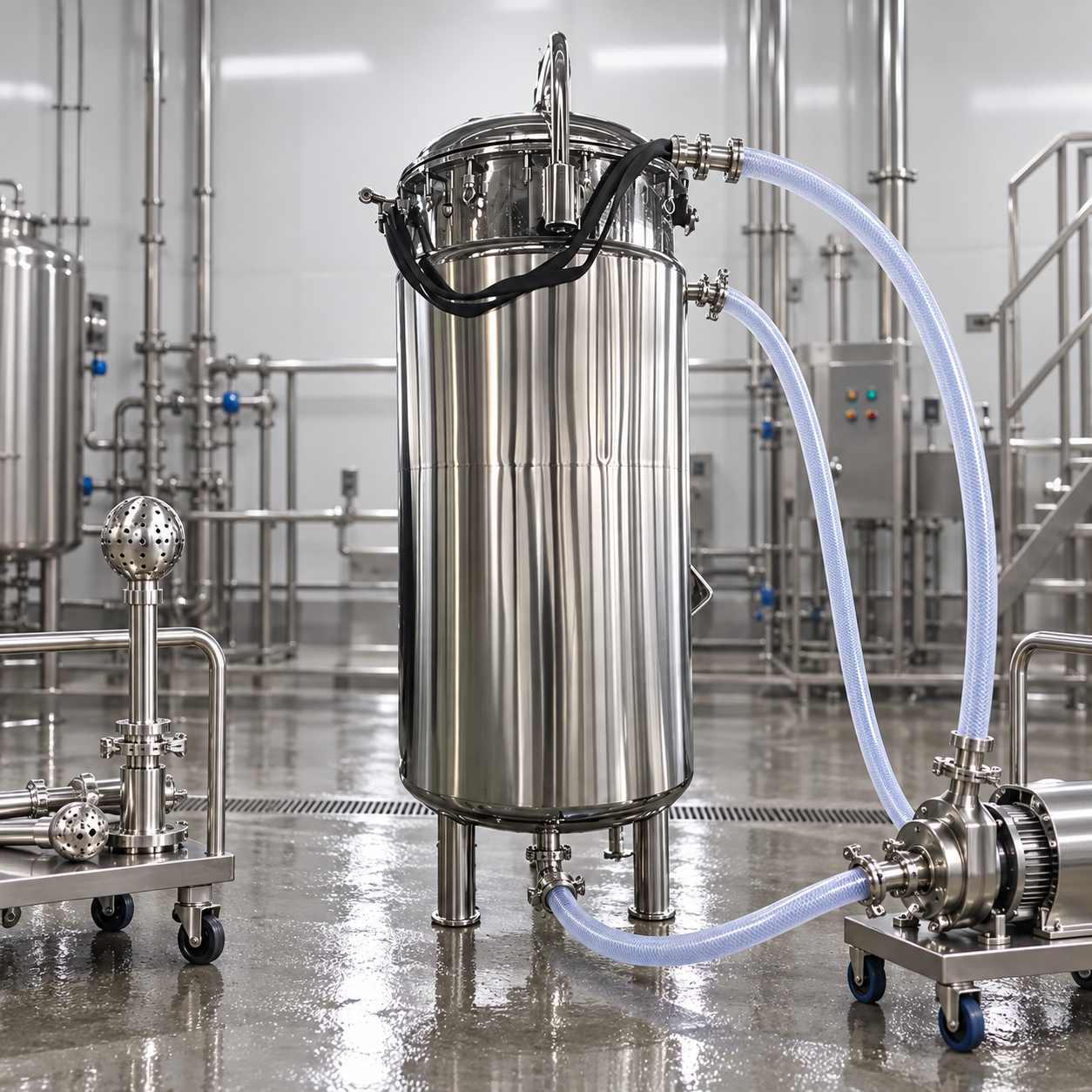
Mixing tank nitrogen blanketing means supplying nitrogen to the vapor space above a liquid so that air ingress is controlled while the tank fills, drains, heats, cools, and mixes. It is not simply a nitrogen hose connected to a nozzle. A workable specification must define the product and oxygen-control objective, vessel pressure and vacuum limits, normal and emergency venting, gas quality, credible flow cases, instrumentation, and safe access. Whether blanketing is needed at all depends on the actual product and process hazard assessment. This guide helps buyers assemble those inputs and review a supplier proposal; it is not a pressure-setting or inerting procedure for an unverified vessel.
First decide what the nitrogen blanket must achieve
Different objectives call for different evidence. A moisture-sensitive ingredient may need a specified dew point and controlled opening practice. An oxidation-sensitive product may require a limit on headspace oxygen and proof that the liquid quality survives the complete batch. A flammable vapor service requires a formal process-safety basis; a slight positive pressure alone is not proof that a mixture cannot ignite. The buyer should state the product composition, temperature range, batch size, agitation method, addition sequence, exposure during sampling, and the consequence of losing the nitrogen supply. A safety specialist must establish any allowable oxygen level from the actual materials and operating conditions, rather than copying a generic percentage from another plant.
Blanketing and purging are related but different. A continuous blanket maintains the specified headspace condition during operation. A purge changes the atmosphere from an initial condition toward a target before startup or after opening. If the process needs both, specify them separately, including how completion is verified. Likewise, nitrogen over the liquid does not automatically remove dissolved oxygen already in the product. The qualification test may need both headspace and product measurements.
Define the vessel boundary before selecting hardware
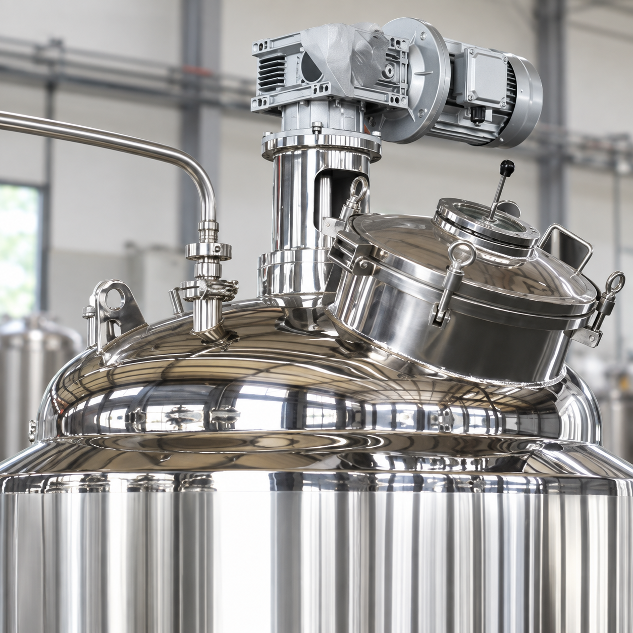
Start with the actual tank drawing and design documents: shell and head, manway, gaskets, agitator seal, sample port, sight glass, feed and discharge nozzles, cleaning connections, instruments, and connected piping. Any opening or leak path can defeat a nominally controlled headspace. Confirm the tank’s permitted internal pressure and external-pressure or vacuum limits as separate values. Do not infer either from wall thickness, a vendor photograph, a motor nameplate, or the presence of a pressure gauge. The permitted range must come from the approved design and applicable project requirements.
The blanket gas enters a headspace that changes with liquid level and temperature. Mixing can generate foam or vapor; heating and cooling can expand or contract the gas; transfer can displace it faster than a small regulator can respond. A process sketch should show the nitrogen supply and isolation, filtration if required, control device, pressure sensing location, normal outlet, emergency relief path, condensate handling where applicable, and any vapor-treatment system. Each item needs an owner and an agreed battery limit. A proposal that shows only a regulator and an inlet nozzle leaves crucial interfaces unresolved.
Normal inbreathing, outbreathing, and upset cases
When product is pumped out, the headspace grows and the tank may need replacement gas. When product is pumped in, gas must leave without exceeding the allowable pressure. Changes in temperature, vapor generation, agitation, and cleaning can add to those demands. Work through credible simultaneous cases, not only the nominal pump rate. For example, an outlet pump operating during cooling may create a different inbreathing demand from discharge alone. A fill operation with heating or foaming may change outbreathing conditions. The appropriate design method and margins depend on tank service, applicable codes, and the pressure boundary.
Normal pressure control is not a substitute for independent overpressure and vacuum protection. Verify that a failed-open nitrogen device, blocked vent, unexpected gas supply pressure, vapor release, or fast transfer cannot put the vessel outside its approved limits. The relief and vent arrangement should be reviewed with the vessel designer and process-safety team. Do not raise a blanketing setpoint or restrict the outlet simply to reduce nitrogen use. EPA guidance notes that many fixed-roof storage tanks cannot withstand significant pressure or vacuum, so vent settings must be considered against the actual tank design; the same caution applies before adapting a mixing vessel to a different service. EPA storage-tank overview.
Decision table for a buyer’s specification
| Design question | Evidence to request | Common review mistake |
|---|---|---|
| Why is nitrogen used? | Product-quality or hazard objective, affected batch stages, and acceptance method | Calling every nitrogen connection an inerting safeguard |
| What is the vessel limit? | Approved pressure and vacuum design basis, drawing, and connected-equipment limits | Using regulator settings as proof of vessel strength |
| How much gas is needed? | Maximum fill and empty rates, temperature cases, vapor generation, and supply availability | Sizing only from nominal tank volume |
| Where does displaced gas go? | Normal vent route, relief route, emissions or vapor-treatment requirement | Assuming the tank can vent freely into the work area |
| How is loss of control detected? | Pressure and oxygen monitoring rationale, alarms, failure response, and test plan | Relying on one unverified gauge |
| How is access made safe? | Isolation, atmospheric testing, confined-space procedure, and emergency response | Treating nitrogen as harmless because it is not toxic |
The table is a procurement screen, not a universal equipment recipe. The values and protective functions belong in the project’s controlled calculations and hazard review.
Pressure control, monitoring, and failure response
A blanketing control device should respond to the real headspace pressure while respecting the vessel’s limits and the normal vent arrangement. The sensing point must represent the tank, not merely pressure in a distant supply line. Instrument range, connection location, isolation valves, condensate, cleaning exposure, and calibration access all matter. For a mixing vessel, check whether agitation, vapor, foam, or a changing product level can disturb the sensing connection. Coordinate the pressure-control logic with existing tank controls rather than adding an independent device whose setpoints conflict with the fill sequence or cleaning mode.
Define what happens when nitrogen supply is low, a valve sticks open or closed, a pressure signal fails, or the vent becomes unavailable. The response may be an alarm, a controlled process stop, a transfer interlock, or another engineered measure, depending on the consequences. It is not safe to prescribe one response for every plant. During acceptance, simulate the agreed faults in a controlled manner and document the observed response. Do not test a vessel by intentionally exceeding its limits. The U.S. Chemical Safety Board’s Marcus Oil case study illustrates how contamination of an inerting supply and inadequate protection can become part of a severe incident; the lesson is to control gas-system interfaces and verify the complete system, not just the nitrogen regulator.
Gas quality and product compatibility
Specify the nitrogen quality needed for the product and the process, not simply “industrial nitrogen.” Depending on service, relevant attributes may include oxygen content, moisture, particles, oil, odor, and microbiological controls. The gas source, distribution line, filters, hose, fittings, and maintenance practices can affect what actually reaches the tank. If the blanket directly contacts food, pharmaceutical, or other sensitive materials, the owner must establish the applicable grade and compliance requirements. A gas certificate at the generator is not necessarily evidence at the point of use after a long distribution system.
Also check product and material compatibility in both normal operation and cleaning. Gaskets, seals, flexible connectors, and instruments may see nitrogen, process vapor, condensate, cleaning fluid, and temperature cycles. A compatibility review that covers only the stainless shell is incomplete. Where oxidation or moisture ingress is the objective, use a product-specific acceptance test: take controlled samples at relevant points in the batch, record headspace condition and process state, and compare results with the agreed quality criterion. Do not equate a stable pressure trace with proven product protection.
Safety: nitrogen can displace breathable air
Nitrogen is not a breathable atmosphere. Leakage, venting, or entry into a nitrogen-filled vessel can create an oxygen-deficient environment without a useful warning from human senses. Plan vent discharge and possible accumulation zones, especially indoors or in pits. Specify isolation and atmospheric testing before entry, and ensure the site’s confined-space program governs inspection and cleaning. The CSB nitrogen-asphyxiation bulletin documents this hazard. The site hazard assessment determines where fixed or portable oxygen monitoring, ventilation, permit controls, and rescue arrangements are needed.
Opening a manway for sampling or cleaning changes the system from a closed blanket to an open process boundary. The procedure should state how gas flow is isolated or controlled, how workers confirm the atmosphere, and how the vessel returns to service. A purge performed after maintenance should be planned and measured; never assume that a timed gas flow by itself proves the desired internal atmosphere. If nitrogen is used to manage a flammable atmosphere, the full ignition-source and static-control strategy still requires review. Nitrogen does not make unsuitable electrical equipment or unsafe maintenance practices acceptable.
Factory acceptance and site commissioning
Agree on the acceptance plan before fabrication. At the factory, review the as-built nozzle schedule, material and gasket records, pressure boundary, regulator and instrument documentation, valve orientation, relief devices, and access for inspection. Verify pressure sensing and control direction with a safe test setup. Confirm that the supplied assembly matches the P&ID and that every deviation is recorded. A factory demonstration can verify components and logic, but it cannot prove the installed nitrogen supply, final vent route, building ventilation, or real product behavior. Those belong in site commissioning.
At site, verify the source and point-of-use gas quality, installed piping, isolation, alarms, vent discharge, operating sequence, and response during representative fill, drain, heat, cool, and agitation conditions. Record pressure and any oxygen or product-quality measurements with timestamps and process state. Demonstrate safe behavior after supply loss or instrument failure using an approved test method. Resolve any unresolved relief, atmosphere, or compatibility issue before production. The final operating procedure should contain normal limits, alarm response, startup and shutdown, maintenance isolation, and change-control triggers.
What to send with the RFQ
Give bidders the product identity and safety information, batch volumes, liquid properties, maximum fill and empty rates, operating and cleaning temperatures, vapor and foam behavior, expected opening frequency, vessel design limits, existing drawings, gas source quality and pressure, plant location, vent or vapor-treatment destination, and the required acceptance evidence. Ask each supplier to mark which party owns the nitrogen source, regulator, control valves, sensing, relief, vent piping, instrumentation, wiring, commissioning, and training. A comparison without these boundaries may make a low bid look complete when essential safety work is excluded.
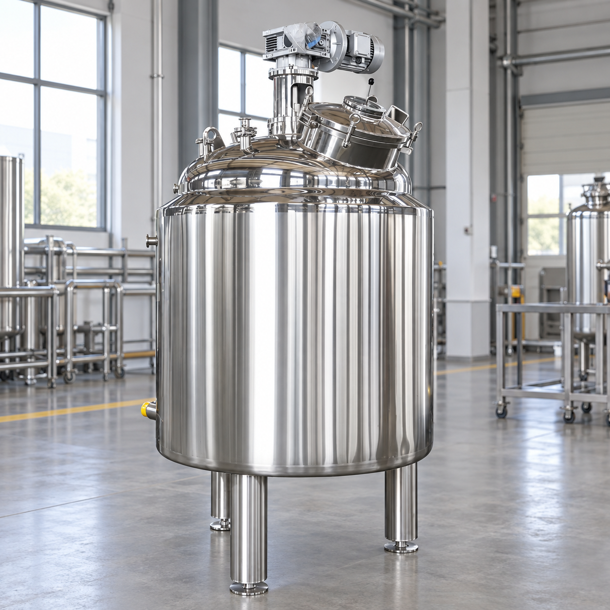
For the physical vessel, review the heated stainless steel mixing tank product page and the broader mixing tank range. These examples establish relevant vessel geometry only; a project-specific blanketing package, pressure capability, and hazardous-area suitability must be independently verified. Related planning guides cover nozzle layout, vacuum versus atmospheric mixing, and foam control. Each addresses a separate decision that can affect the gas-space design.
Educational video: inerting and purging
The following IIT Roorkee/NPTEL chemical-process-safety lecture explains inerting and purging principles. It is an educational supplement, not a design approval for this tank.

Open the IIT Roorkee lecture on YouTube.
Frequently asked questions
Does a nitrogen blanket automatically make a mixing tank explosion-proof?
No. The complete process, oxygen-control basis, electrical installation, ignition hazards, pressure boundary, venting, and operating procedures require a project-specific assessment. A nitrogen connection or positive-pressure gauge is not a certification.
Can the same regulator setting be used for every tank?
No. The setting and protective arrangement must be derived from the approved vessel limits, process conditions, supply characteristics, normal transfer cases, and relief design. Copying a setting from another tank can be unsafe.
How should buyers prove that blanketing protects product quality?
Define a product-specific acceptance criterion, measure the relevant atmosphere and product condition during representative operations, and retain the test record. Pressure alone does not prove oxygen or moisture control.