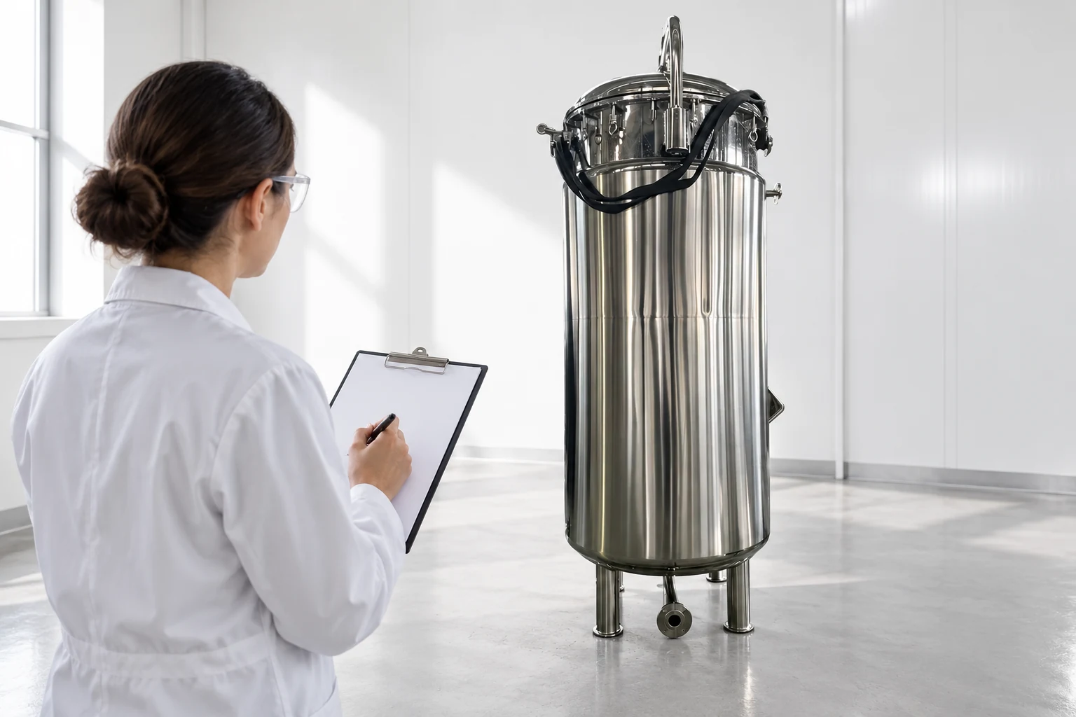
A heat exchanger commissioning checklist should establish mechanical readiness, safe operating conditions, instrument reliability, and a documented performance baseline before production handover. Recording an outlet temperature alone is insufficient: flow, inlet conditions, pressure drop, utility state, and measurement uncertainty affect the result. Define the acceptance conditions before testing, distinguish factory evidence from site verification, and close material deviations before release. The checklist below is a framework for industrial liquid-service equipment; final procedures must follow the exchanger manufacturer’s instructions and the site’s approved engineering and safety requirements.
Agree the commissioning boundary and acceptance basis
Start by identifying the exchanger, connected piping, pumps, valves, instruments, controls, and utilities included in the test. Clarify interfaces with systems outside the supplier’s scope. A skid can be correctly assembled while its site connections remain incomplete or unsuitable. Assign responsibility for test planning, safe isolation, measurement, data review, and final acceptance. Include the people who will operate and maintain the installed equipment.
State the required duty, permitted operating envelope, fluid properties, available utilities, and expected operating modes. Specify which conditions can be demonstrated during commissioning and which require later process verification. If a test uses water instead of the production fluid, explain that limitation. Agree how off-design test results will be evaluated rather than comparing them directly with a design guarantee stated for different conditions.
Confirm identity, drawings, and installation readiness
Compare the equipment identity and connections with approved drawings and component records. Verify orientation, support, service clearance, and accessible isolation points. Look for installation changes that have not reached the documentation. Review whether piping loads and thermal movement were addressed by the responsible designers. Do not use the exchanger’s connections as a convenient means of forcing misaligned site pipework into position.
For removable components, confirm the required maintenance envelope and lifting arrangements. Fixed-tubesheet and other exchanger constructions have different service requirements; refer to the fixed tubesheet versus floating-head guide for procurement context. Final installation decisions must follow the selected equipment’s verified design. Resolve missing connections, unsupported lines, and unclear isolation arrangements before attempting a live operating test.
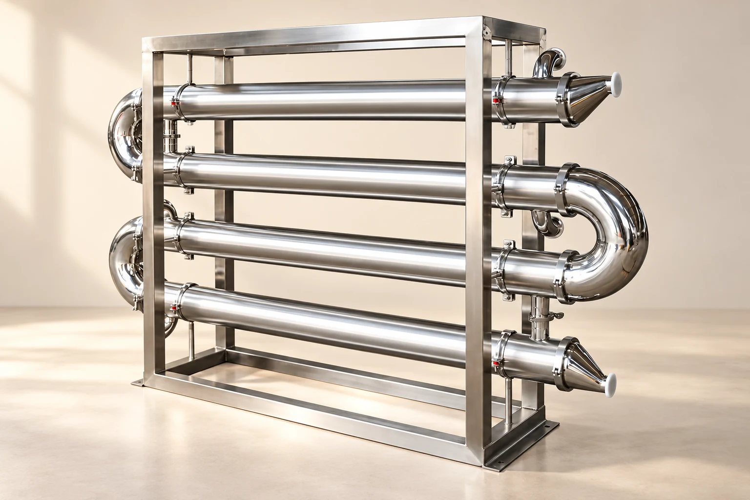
Build a commissioning checklist with evidence fields
Each item should identify its requirement, verification method, result, responsible person, and supporting record. A checkbox is useful for workflow, but it should not replace measured results or documented observations. The following table gives review points without specifying universal test pressures, temperatures, or acceptance tolerances. Those must be approved for the actual equipment and fluids.
| Этап | Проверить | Record or release evidence |
|---|---|---|
| Mechanical readiness | Identity, orientation, supports, access | Approved drawing comparison and inspection record |
| System readiness | Correct routing, isolation, drains, vents | Verified line-up and defined boundaries |
| Instrument readiness | Range, units, calibration, locations | Instrument list and current verification records |
| Safe startup | Limits and operating sequence | Approved procedure and trained responsible staff |
| Steady test | Flows, temperatures, pressures, stability | Time-stamped baseline data and test conditions |
| Functional checks | Controls, alarms, specified responses | Approved test method and observed outcomes |
| Передача | Deviations, drawings, maintenance, training | Reviewed completion package and release decision |
Address pressure, stored energy, and isolation
Both fluid circuits need clearly documented operating limits and isolation arrangements. Different sides can have different ratings. Consider the conditions created by startup, shutdown, thermal expansion, pump operation, and maintenance. Protection must suit the installed system, including downstream restrictions and trapped volumes. A nameplate is important evidence, but it does not alone demonstrate that site operation will remain inside every limit.
Use the approved site procedures for isolation, draining, depressurization, and verification before opening equipment. Never invent a commissioning pressure-test value from a general checklist. HSE’s pressure systems overview explains the underlying hazards and relevant Great Britain framework. Apply the requirements of the actual installation market and consult competent personnel for testing and protection. Keep the approved procedure with the commissioning records.
Check instrumentation before judging thermal performance
Identify all temperature, pressure, and flow instruments used in the baseline. Confirm measurement locations and units. The recorded temperatures must represent the streams being evaluated, not an upstream bypass or a mixed header with an unrecognized contribution. Where sensors are installed in thermowells, account for the installation and response when selecting a stable recording period. Calibration alone cannot fix an unrepresentative measurement location.
Review the expected resolution and uncertainty relative to the temperature changes and pressure drops being measured. A small temperature difference can be especially sensitive to instrument errors. Record how measurements are synchronized. If flows and temperatures change during data collection, a calculated heat balance can be misleading. Define a stability criterion and retain the raw observations so reviewers can assess whether the chosen test period was appropriate.
Use a manufacturer-approved startup sequence
Startup must follow the exchanger’s construction, fluid service, and approved instructions. Verify line alignment, available utilities, and the condition of vents and drains before introducing the process streams. Avoid assigning one generic sequence to every exchanger. Steam, refrigerant, hot liquids, and temperature-sensitive products can require quite different procedures. The responsible engineers should identify how the installation controls pressure transients and thermal stresses.
During startup, observe pressure, temperature, leakage, vibration, and control behavior using the approved acceptance criteria. Stop or hold the test when a defined limit or abnormal condition is encountered. Do not conceal an unstable startup by recording only the final steady reading. Include the operating events in the test record, because they may explain later performance or reveal a maintenance and training requirement.
Establish a sensible-heat performance baseline
For a single-phase stream with suitable property information, the heat rate can be estimated as Q = m_dot × cp × temperature change. Here Q is watts, m_dot is kilograms per second, cp is joules per kilogram-kelvin, and temperature change is kelvin. Use properties appropriate to the fluid and temperature range. This simplified expression is not sufficient for phase change, major property variation, or a poorly characterized mixture; those cases require a suitable enthalpy method.
As an illustrative arithmetic check, a water-like stream at 1.0 kg/s, with an assumed cp of 4,180 J/(kg·K) and a 10 K change, gives 41,800 W. These are hypothetical teaching inputs, not a guaranteed product duty or commissioning tolerance. The LearnChemE material and energy balance resources provide the underlying principles. Record actual inputs, property sources, and limitations for the installed equipment.
Compare the hot-side and cold-side heat rates where both can be estimated reliably. A difference may reflect measurement uncertainty, losses, unstable conditions, property assumptions, or an unrecognized stream. It does not automatically prove exchanger damage. Agree an acceptance method based on the test design and uncertainty rather than borrowing an arbitrary percentage. Retain sufficient data to investigate a mismatch before issuing a performance conclusion.
Record hydraulic conditions alongside temperatures
Pressure drop should be documented with flow rate, fluid state, temperature, and measurement points. A clean baseline is useful only when later readings are compared under relevant conditions. A higher pressure drop at a higher flow is not automatically evidence of fouling. Similarly, a lower outlet temperature may result from changed inlet conditions rather than improved heat transfer. Record bypass positions and control-valve behavior that could influence the result.
Review pump operation and utility distribution as part of the system. If the actual flow falls short of the design assumption, determine whether the constraint lies in the exchanger, connected piping, pump, or control arrangement. Do not respond by altering equipment limits. The shell-and-tube maintenance guide provides complementary service-planning context after the baseline has been established.
Verify controls and responses with approved methods
Check the intended controller behavior across the agreed operating range. Confirm that alarms reach the responsible operator and that specified responses occur. Test methods should be chosen so they do not expose people or equipment to uncontrolled conditions. Simulated signals or staged functional checks may be appropriate when approved by the responsible team. Record both the method and the observed response.
Include power restoration, communication loss, and restart behavior when these affect the supplied controls. Verify the distinction between a normal control action and an independent protective function. Keep software and configuration identity in the handover package where relevant. Resolve unexplained oscillation, inconsistent units, and unclear fail-state behavior before final release. Operators should receive instructions that match the installed and tested configuration.
Hand over a baseline that maintenance can use
The completion package should contain approved drawings, equipment identity, operating limits, test procedures, actual baseline data, instrument records, deviation decisions, and maintenance instructions. State the conditions under which the performance was demonstrated. Preserve open issues with owners and deadlines; a handover signature should not silently turn incomplete evidence into a passed test. Include training and access requirements for routine service.
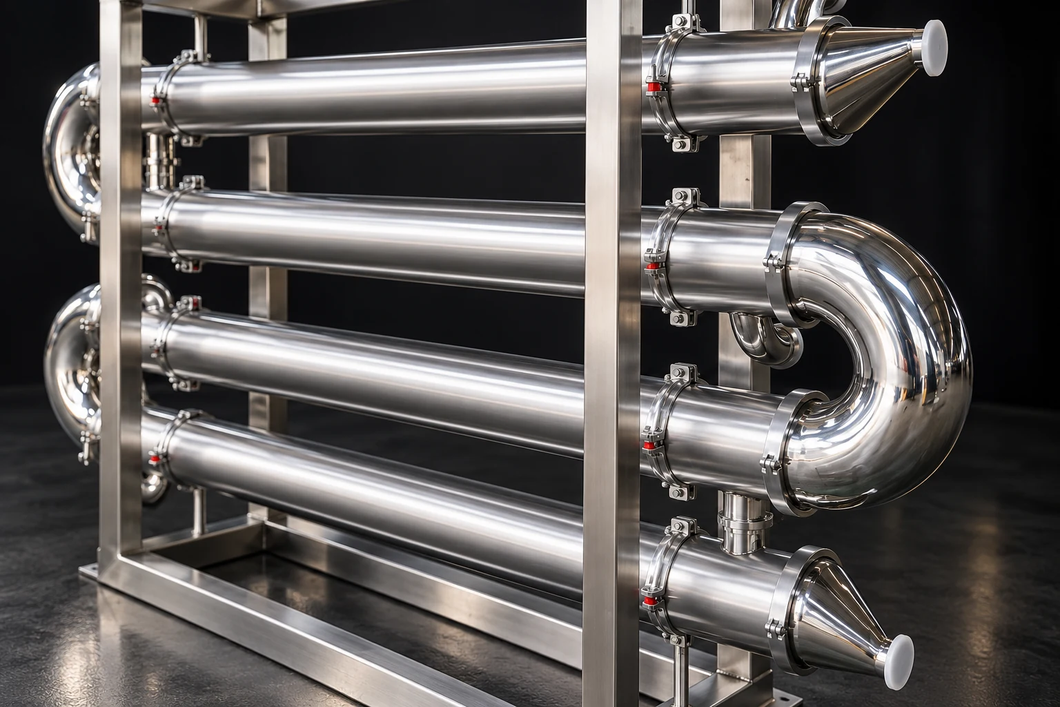
Для sanitary tubular heat exchanger enquiry, request this package in the quotation and agree what is factory-supplied versus site-generated. The wider heat exchanger introduction и fouling guide support operating context and later troubleshooting. The commissioning page’s focus is a documented starting point, not a substitute for those decisions.
Educational video and references
LearnChemE’s Heat Exchanger simulation from the University of Colorado Boulder explains temperature profiles and driving forces. It helps readers interpret thermal measurements; it is not a field startup procedure.
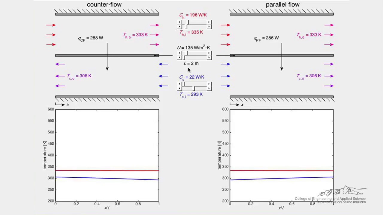
Watch Heat Exchanger (Simulation) by LearnChemE
For further fundamentals, see Ресурсы компании LearnChemE по передаче тепла. Use the manufacturer’s actual instructions for sequence, ratings, materials, and test limits.
Часто задаваемые вопросы
Is one outlet-temperature reading a complete performance test?
No. Record inlet conditions, flows, other relevant temperatures, hydraulic conditions, and stability. Evaluate the result against defined acceptance conditions and measurement limitations.
Can a water test prove performance with every production fluid?
No. Different properties and operating conditions can change performance. State what the water test demonstrates and what requires calculation or later process verification.
What is the most useful maintenance baseline?
A time-stamped set of thermal and hydraulic measurements with clear fluid, flow, inlet, instrument, and configuration information. Comparable conditions make later trends interpretable.