

An automatic tube cleaning system for a heat exchanger periodically moves a cleaning element through compatible tubes while the cooling circuit operates. Its value depends on the deposit, tube geometry, water chemistry, and reliable recovery of every cleaning element. It is usually a water-side fouling-control option, not a universal replacement for chemical treatment or shutdown inspection. Before requesting a quotation, establish which side fouls and whether the exchanger was designed to accept an online cleaning arrangement. A photograph of an accessible tube sheet cannot establish that compatibility.
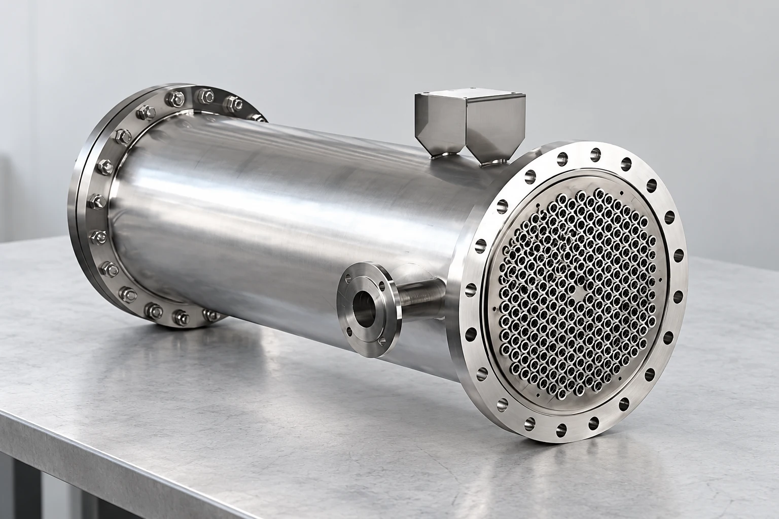
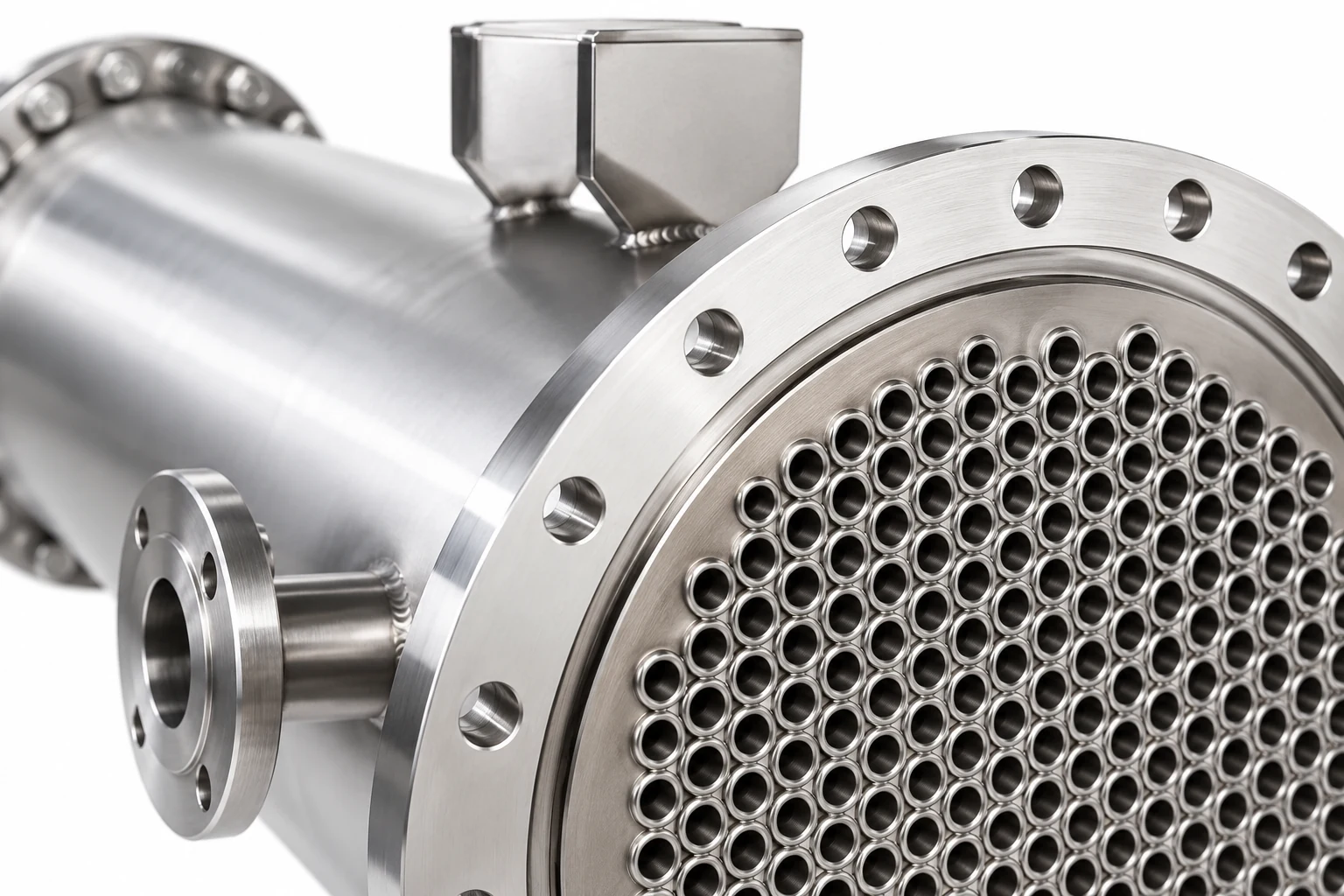
This guide addresses selection and verification of an automatic system. For broader deposit causes, use our heat exchanger fouling guide. YIYI’s fixed-tube-sheet exchanger provides a relevant equipment reference; the published product images do not confirm an integrated automatic cleaning package.
Start with the fouling location and deposit
Review the maintenance history before comparing cleaning technologies. Tube-side suspended solids, biological films, mineral scale, process-side deposits, and shell-side accumulation are different problems. A cleaning element traveling inside a tube cannot clean the outside of that tube. Likewise, a mechanism that discourages soft-film buildup may not remove an established hard scale layer. Ask the plant team where the deposit was found during the last inspection and retain photographs, sample results, cleaning records, and operating conditions.
Avoid diagnosing fouling from one temperature difference alone. A warmer coolant inlet, reduced flow, changed production load, or inaccurate sensor can imitate a fouling symptom. Compare operation at similar loads and record both stream inlet and outlet temperatures with flow and differential pressure. Use the Список контрольных процедур по пусконаладке теплообменника to establish a traceable clean baseline rather than treating the first available reading as normal operation.
How online cleaning arrangements differ
Sponge-ball systems introduce suitable cleaning balls into a compatible water stream, transport them through the tubes, collect them downstream, and return them to the injection arrangement. Their success requires a verified transport and recovery path. Tube diameter, ball behavior in the actual water, flow distribution, strainers, collection screens, and operating range all matter. The system designer must establish how every tube is reached and how losses are detected.
Some brush arrangements retain a brush for individual tubes and reverse the flow to move it between designated ends. Those systems have different installation and operating requirements from circulating balls. An offline tube-cleaning tool used during a shutdown is a third category. It may offer controlled access but does not provide continuous online cleaning. Do not accept a quotation that uses these names interchangeably without a diagram showing the intended flow path and the maintenance method.
Match the mechanism to the actual exchanger
The first mechanical review should use drawings, not just a brochure. Identify straight tubes or U-tubes, tube bore, length, pass arrangement, tube sheet layout, return chambers, restrictions, surface condition, and access for inspection. Ask whether the proposed cleaning element must pass through bends or transitions and whether the supplier has verified that exact geometry. A cleaning method suitable for one straight-tube water circuit is not automatically suitable for a sanitary multipass assembly.
Confirm the pressure boundary separately from the cleaning mechanism. Injection connections, isolation valves, collection vessels, and modified piping must be reviewed for the design conditions and applicable project requirements. Obtain written approval before adding connections to existing equipment. The supplier should also explain how the system behaves at startup, low flow, shutdown, reversal, and loss of its controller or power supply. Compatibility must include abnormal operation, not only a nominal flow-rate demonstration.
Use a selection table with clear rejection conditions
The following table is a buyer’s screening tool, not a universal installation specification. Its acceptance conditions require confirmation by the exchanger and cleaning-system designers. Water treatment remains a separate responsibility: the U.S. Department of Energy’s side-stream filtration guidance explains why removing suspended material does not eliminate the need to control dissolved constituents and microbiological conditions.
| Пункт обзора | Доказательства для запроса | Reason to pause the selection |
|---|---|---|
| Deposit and location | Inspection photographs and deposit characterization | Main deposit is outside the tubes or not removable by the proposed mechanism |
| Tube path | Approved bore, bends, passes, and return-chamber drawings | Cleaning elements cannot traverse the actual path reliably |
| Water chemistry | Operating analysis and treatment responsibilities | Proposal assumes mechanical cleaning replaces chemical control |
| Recovery and loss detection | Collection diagram, counting method, and loss response | Missing elements cannot be detected or located |
| Рабочий диапазон | Verified minimum and maximum transport conditions | System only works at a flow the plant rarely maintains |
| Доступ для обслуживания | Isolation procedure and component removal space | Screens or valves cannot be serviced safely |
| Принятие | Baseline, trial duration, instrumentation, and success criteria | Claimed savings lack defined comparison conditions |
Integrate water treatment and filtration
Automatic tube cleaning should fit the wider water-management program. Suspended solids removal can reduce one source of deposition, but dissolved minerals and biological activity require their own controls. Poor treatment can leave the cleaning system repeatedly addressing symptoms. Conversely, a cleaning mechanism should not introduce material that disrupts established treatment, filtration, or downstream operations. Assign a responsible person for chemical compatibility and water sampling.
Эт DOE cooling-water efficiency guidance is useful background for understanding the relationship between operating water conditions and heat-transfer performance. It is not an endorsement of any cleaning package or a guarantee of energy savings. Set the treatment plan from the actual water source, temperatures, materials, and operating duty. If the process changes, revisit the assumptions rather than retaining the old cleaning cycle automatically.
Specify monitoring and a response to losses
A display showing that the injection pump ran is not proof that every tube was cleaned. Request the supplier’s method for observing transport, checking inventory, and identifying incomplete recovery. Define what happens when recovery falls below its agreed acceptance criterion. The response may require stopping injection, checking collection equipment, investigating a restriction, or isolating the circuit under an approved procedure. The exact response belongs in the operating instructions.
Record useful operating data alongside each cleaning cycle: time, plant load, water flow, differential pressure, temperature readings, element inventory, and alarms. Avoid promising a fixed universal interval. A cycle appropriate for a stable cooling-water service can be unsuitable during turndown or a major change in solids loading. The commissioning team should identify which readings trigger review and who is authorized to change the operating settings.
Demonstrate performance before claiming savings
Establish the reference period before installing or enabling the system. Check sensor calibration, confirm measurement locations, and collect enough stable operating data to distinguish normal variation from degradation. Define whether success means slower loss of thermal performance, reduced planned cleaning frequency, improved availability, or another measurable outcome. State the operating conditions for the comparison and exclude periods with unrelated maintenance or process changes where appropriate.
A trial should include the complete recovery arrangement and its maintenance burden. Record cleaning-element replacement, screen servicing, power use, operator time, and any interruption. A reduction in shutdown cleaning may be valuable even when a simple electricity comparison is inconclusive. Keep the commercial evaluation tied to documented plant performance. Vendor percentages without a comparable duty, baseline, and measurement method are insufficient for a purchase decision.
Plan safe access and commissioning
Online operation does not mean that maintenance can be performed on a pressurized circuit. Document isolation, depressurization, drainage, and verification before opening collection equipment or removing screens. Match the procedure to the plant’s energy-control rules. Site personnel must determine the actual isolation points and approved work method under the applicable control-of-hazardous-energy requirements.
Commissioning should confirm identification, orientation, flow direction, installation clearances, controller logic, alarms, and recovery at the agreed operating conditions. Retain a punch list and separate unresolved defects from accepted performance. Include a shutdown inspection strategy: online cleaning cannot establish tube wall integrity, gasket condition, corrosion rate, or pressure-boundary fitness. The руководство по обслуживанию кожухотрубного пучка covers complementary access questions.
Understand the thermal baseline
The neutral educational video below explains heat-exchanger behavior through a simulation. It supports understanding the thermal measurements used in a cleaning trial; it does not demonstrate an automatic tube-cleaning mechanism or validate a particular installation. Use it with the written measurement plan, not instead of the exchanger drawings and system-specific instructions.
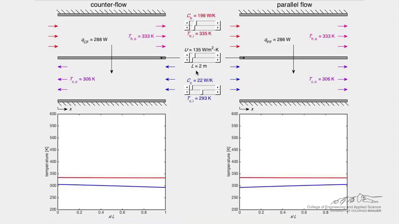
Посмотрите видео «Теплообменник (симуляция)» от LearnChemE
Prepare an RFQ that suppliers can answer
Send the exchanger drawing and identification, service description, both fluid conditions, operating range, recent water analysis, deposit evidence, and cleaning history. Describe the available pipework space and whether the project is a retrofit or new installation. Ask for a compatibility statement, recovery arrangement, component materials, control narrative, maintenance instructions, and a list of exclusions. Require the proposal to distinguish confirmed performance from assumptions that need a site survey.
For a YIYI exchanger project, request review of the approved exchanger configuration and the interface to any separately supplied cleaning package. Do not infer automatic-cleaning capability from stainless construction or an exposed tube sheet. A useful next step is a joint mechanical and operating review with the exchanger supplier, cleaning-system specialist, water-treatment team, and plant operator before accepting a savings estimate or final price.
Часто задаваемые вопросы
Does an automatic tube cleaning system remove every type of fouling?
No. Performance depends on the deposit, its location, and the cleaning mechanism. A tube-side traveling element cannot remove shell-side deposits. Established hard scale may need another approved cleaning method. Confirm suitability from deposit evidence and a documented trial.
Can it be retrofitted to any shell-and-tube exchanger?
Compatibility must be verified. Tube geometry, pass arrangement, transport conditions, pressure-boundary interfaces, collection space, and maintenance access can limit retrofit options. Obtain an installation review rather than relying on a generic model description.
Does it replace water treatment?
It should not be assumed to do so. Mechanical cleaning and filtration address different mechanisms from dissolved-mineral and biological control. Keep a water-treatment program appropriate to the actual service and materials.
What should prove that the system works?
Use defined operating conditions, a clean baseline, transport and recovery checks, reliable temperature and flow measurements, and a documented trial. Include maintenance and losses in the evaluation, and retain evidence for every claimed improvement.


