

Rotary lobe pump speed for high-viscosity fluids should be selected from the required delivered flow, displacement, internal slip, inlet filling conditions, differential pressure and drive torque. Higher speed is not automatically a better solution: a viscous product may not enter the moving cavities fast enough, while power, temperature or product damage can become limiting. Ask the supplier to confirm the speed range for the actual fluid and installation. The useful selection is an operating envelope covering startup and steady production, rather than a single catalogue maximum or a universal RPM recommendation.
Define what high viscosity means for the duty
Provide viscosity together with measurement temperature and method. A value measured at a warm laboratory condition may be a poor representation of a cold production startup. If the product is shear-dependent, provide the available relationship between viscosity and shear conditions rather than treating one number as a fixed property. Include density, solids, entrained air and any tendency to set or separate during a stoppage.
Describe the product outcome that must be preserved. Examples include particle integrity, acceptable temperature rise, emulsion condition or texture. The pumping requirement is not fulfilled if the flow target is met but the material becomes unsuitable for the next stage. Agree on a practical product-quality check with the process team before comparing pumps.
Keep product transfer and cleaning duties separate in the enquiry. Cleaning liquid can have very different viscosity, temperature and flow requirements. A speed suitable for transferring a thick product is not necessarily the speed needed for the approved cleaning sequence.
Use displacement as a starting point
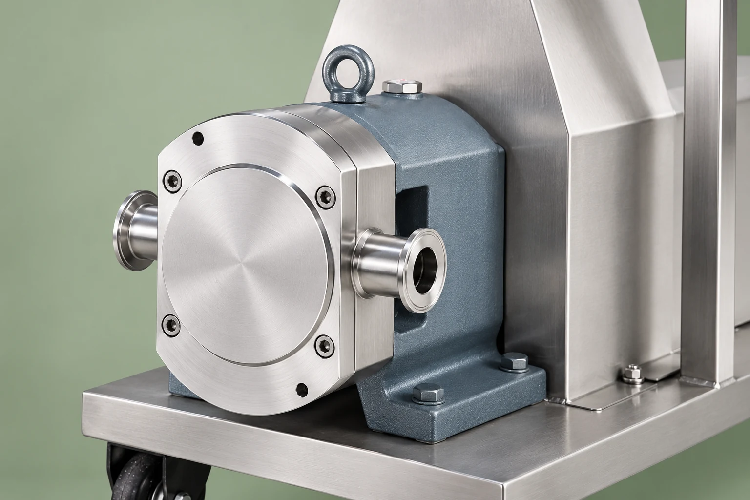
For a rotary positive-displacement pump, the ideal flow relationship is Qideal = Vd × n, where Vd is displacement per revolution and n is rotational speed. If displacement is in litres per revolution and speed in revolutions per minute, the result is litres per minute. Actual delivered flow differs because of slip, filling conditions and the state of the equipment.
For example, an assumed displacement of 0.50 litres per revolution at 200 revolutions per minute gives an ideal flow of 100 litres per minute. This is an arithmetic illustration only. It is not a specification for the pictured pump and cannot be used to select equipment without actual displacement and performance information.
El Libro de referencia sobre sistemas de bombeo del Departamento de Energía de los Estados Unidos provides general context for positive-displacement equipment and the importance of the connected system. Use the selected pump’s supplier curves for its real performance. Do not apply centrifugal affinity-law estimates as a substitute for a lobe pump’s confirmed displacement and slip data.
Determine the required delivered flow
Calculate flow from the process requirement and available transfer time. Include charging, displacement, return or recirculation duties where relevant. State whether the rate is continuous or whether the pump must deliver a specified batch within a time window. A process requiring a short peak transfer can have a different selection from one with the same daily volume spread across a shift.
Avoid adding several unexplained margins. A larger batch allowance, shorter transfer time and an additional flow reserve can compound into excessive capacity. Identify which uncertainty each margin addresses, then ask whether variable speed can accommodate the resulting range within the pump’s approved limits.
Also define the lowest useful flow. Some processes require controlled dosing or a slow initial charge. Verify the minimum permitted speed, drive cooling and stable delivery at that point. A pump that reaches the maximum demand but cannot operate reliably at the lower demand may still be unsuitable.
Examine inlet filling before increasing speed
Viscous fluid can create substantial resistance in a long or narrow inlet line. The rate at which the pump’s cavities fill then becomes a key constraint. Review the supply vessel level, outlet geometry, line length, pipe bore, valves, strainers and temperature. A short enlarged suction line may change the feasible operating envelope, but its dimensions require a duty-specific calculation.
Check the most demanding credible case: coldest product, lowest tank level, longest route and the condition before cleaning a strainer. If the pump is supplied through flexible hose, confirm that its bore and permitted vacuum condition remain appropriate. Do not assume that the external hose diameter describes the internal flow passage.
El NPTEL lesson on suction head and vapour pressure explains why temperature and inlet pressure need to be reviewed together. Apply supplier suction criteria for the lobe pump; a maximum speed stated without inlet conditions is incomplete selection evidence.
Check pressure, torque and drive suitability
Discharge pressure follows the connected system’s resistance and downstream condition. It is not determined by speed alone. The drive must provide the required torque while respecting the pump, gearbox and motor limits. Ask for the calculation or selection data at the demanding pressure and viscosity combination, including startup.
An illustrative hydraulic power calculation is Phydraulic = Q × Δp when Q is in cubic metres per second and Δp is in pascals. At 0.002 cubic metres per second and a pressure difference of 300,000 pascals, hydraulic power is 600 watts. Real shaft power is higher because of losses. This example describes units; it does not specify motor power, efficiency or an allowable pressure for any product.
Confirm overload protection and the response to a blocked outlet. A positive-displacement pump requires an appropriately reviewed overpressure-protection arrangement. A variable-speed drive can change delivery, but its presence does not replace that protection. Refer to Guía de sistemas de presión de HSE alongside the project’s applicable requirements.
Compare operating cases in a selection table
| Operating case | Main constraint to investigate | Evidence requested from supplier |
|---|---|---|
| Cold product startup | High viscosity and startup torque | Permitted starting procedure and drive selection |
| Normal transfer | Flow at the actual differential pressure | Delivered-flow curve or duty confirmation |
| Low vessel level | Reduced inlet supply margin | Suction assessment at the chosen speed |
| Gentle product handling | Material damage or temperature rise | Product trial and agreed quality criteria |
| Minimum controlled flow | Low-speed stability and motor cooling | Minimum operating speed and control limits |
| Limpieza de la circulación | Different fluid properties and flow demand | Separate cleaning-duty confirmation |
The table organises decisions, not fixed RPM limits. Two products with similar stated viscosity may behave differently because of temperature sensitivity, solids or yield behaviour. The supplier should identify which cases govern the final selection and which remain untested.
Protect product quality during the speed trial
Establish a baseline sample before pumping and agree how downstream samples will be assessed. Record the transfer conditions for each trial rather than comparing samples from different recipes or temperatures. If particle damage matters, use an appropriate particle or texture check; if thermal exposure matters, measure relevant temperatures and hold time.
Avoid promising that all rotary lobe pumps are inherently gentle under every condition. Geometry, clearances, speed, differential pressure and repeated recirculation affect the result. A product can pass through the same equipment several times in a recirculation loop, creating a different exposure from one-pass transfer.
If a reduced speed improves product condition, quantify the impact on transfer time and production sequence. A technically attractive operating point may require a larger pump displacement or a revised batch schedule. Those are explicit tradeoffs to assess before purchasing, not reasons to conceal a failed throughput target.
Set a usable control range
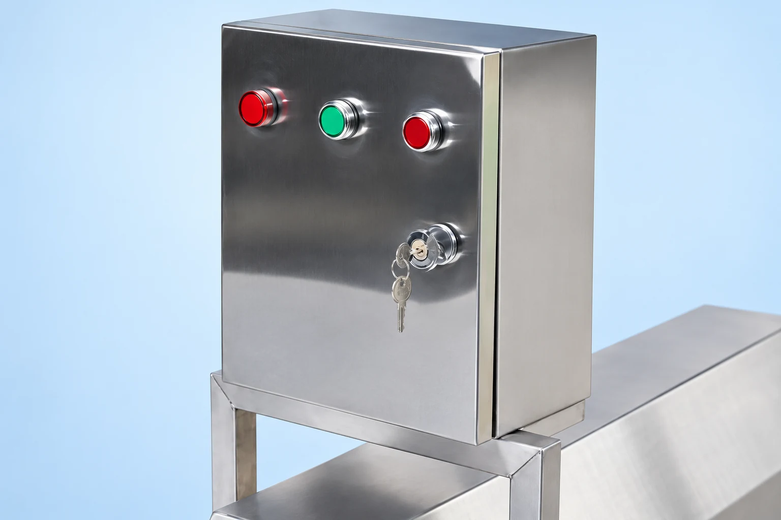
Specify minimum and maximum approved speed in the control system after the duty has been confirmed. Include startup ramps, permissives and any recipe-dependent restrictions. Check whether the operator display shows motor frequency, motor speed or actual pump speed. A gearbox ratio means these numbers cannot be used interchangeably.
Define what happens when the desired flow cannot be reached. Increasing speed without a limit can worsen an inlet problem. A controlled response may involve checking inlet level, temperature or restriction before another speed increase. The exact sequence should follow the supplier and plant review.
Keep maintenance and wear in the performance assessment. Growing clearances can change slip and delivered flow. If the controller repeatedly increases speed to compensate, the underlying wear may remain hidden. Record both the commanded speed and measured result so operators can detect a changing relationship over time.
Confirm the selection with an acceptance test
Prepare a test matrix with startup, normal transfer, low supply level and minimum flow. Measure delivered volume over time, pressure, temperature, actual speed and drive load. Identify the measurement uncertainty and product condition. A water trial is useful for basic operation but does not establish the viscous product duty.
Agree on acceptance criteria before ordering. Specify the required flow range, maximum allowed product change, protection response and permitted operating envelope. Retain the supplier’s curves, test records and final settings with the equipment file. Where the exact product cannot be tested before delivery, state how the installed trial will close the remaining uncertainty.
Utiliza el rotary lobe pump product page to discuss the available configuration. For broader equipment requirements see the rotor pump selection guide, syrup heating and viscosity planning, y batch mixing cycle-time planning.
Formación continua
This independent educational animation explains the moving cavities of a rotary lobe pump. It supports the displacement discussion but does not recommend a particular operating speed for the website’s equipment.
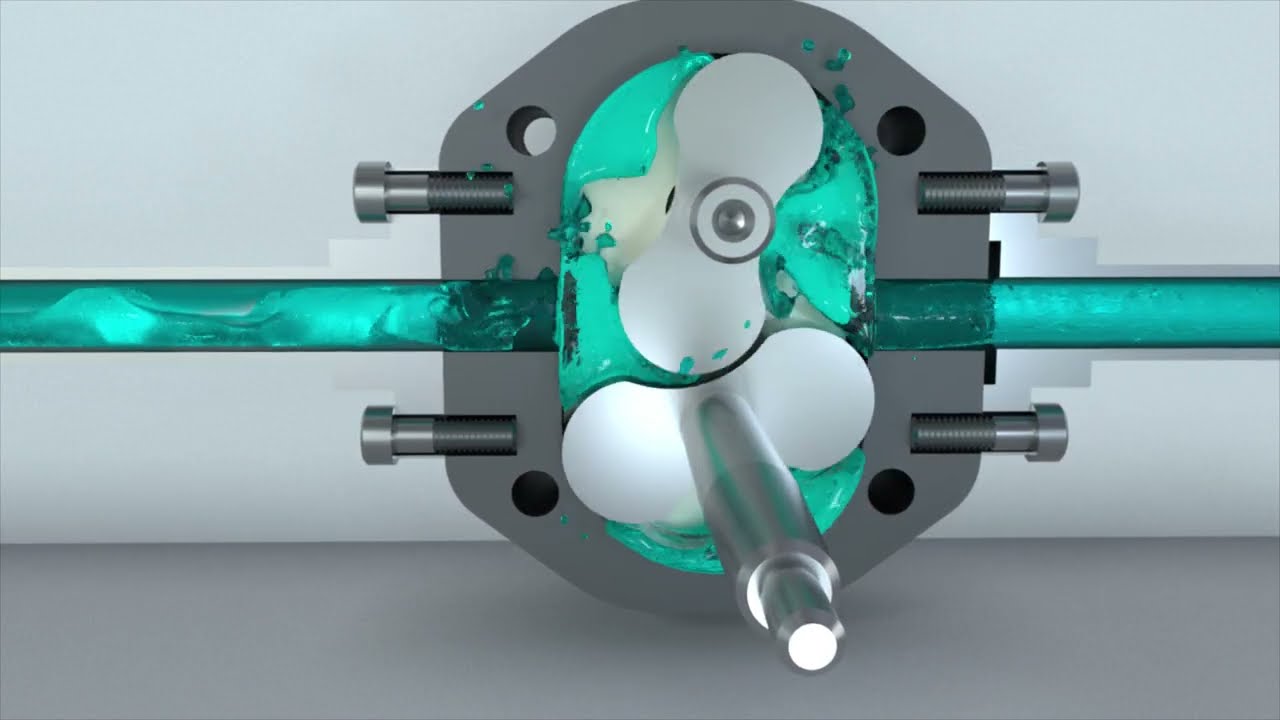
Ver la bomba de cono rotatorio: ¿Qué es? ¿Cómo funciona? por sistemas hidráulicos y neumáticos
Preguntas frecuentes
Is there one recommended RPM for high-viscosity products?
No universal RPM covers all fluids and installations. Select speed using displacement, required delivered flow, viscosity at operating temperature, inlet filling, pressure and drive limits. Request a confirmed operating envelope from the supplier.
Can a larger motor cure low flow?
A larger motor does not remove an inlet restriction or establish that the pump is suitable at a higher speed. Diagnose filling conditions, slip and system resistance, then review pump and drive selection together.
What should a variable-speed pump enquiry include?
Provide maximum and minimum flow, startup and operating fluid properties, suction and discharge layout, pressure range, product-quality limits, cleaning duty and required transfer time. Ask for the permitted speed range and the evidence supporting each operating case.


