

Rotary lobe pump dry running occurs when the pump operates without the liquid conditions required by its seals and other wetted components. A pump that moves air briefly or is described as self-priming is not automatically permitted to run dry. The acceptable condition depends on the exact pump, seal arrangement, speed, temperature, fluid, and any specified support system. Prevent dry running by verifying the manufacturer’s operating limits, maintaining a reliable liquid supply, detecting loss of feed, and defining a controlled stop and restart sequence. Never infer a permitted dry-running duration from a general pump category.
Separate dry running from cavitation
Cavitation involves vapor formation and collapse when local pressure falls below the liquid’s vapor pressure. Dry running concerns insufficient liquid for the equipment’s required lubrication, cooling, or process condition. The two can occur together, but they require different evidence. A starved inlet may first produce unstable flow and later lose liquid entirely. Treating every noise as cavitation can miss a seal-temperature problem or an empty supply tank.
The existing rotary lobe pump cavitation guide explains inlet-pressure diagnosis. For dry-running assessment, add the seal instructions, liquid-presence evidence, and the actual interruption sequence. US Department of Energy pumping-system sourcebook provides background on the pumping principle; it does not establish the limits of a specific installed seal.
Identify which components depend on liquid
Review the complete assembly with the supplier. Mechanical seal faces, elastomeric components, product-lubricated bearings where present, and other wetted parts can have different restrictions. Some configurations use a specified seal support system; others rely on the pumped product. Ask what must be present before starting and what must remain available during operation, cleaning, and standby.
A manufacturer’s statement about one configuration should not be applied to a different seal, rotor material, or operating temperature. Record the full model and relevant configuration identifiers. A replacement seal can change the operating envelope even when the casing and motor are unchanged. The maintenance record should therefore identify parts and instructions rather than only the generic pump name.
Find the realistic loss-of-liquid scenarios
An empty feed tank is only one cause. A closed inlet valve, blocked strainer, collapsed hose, frozen or highly viscous product, gas pocket, transfer interruption, or incorrect changeover can interrupt supply. Cleaning and draining sequences can leave the pump running after useful liquid has disappeared. Review both normal production and maintenance-related modes.
Consider how the inlet behaves during tank drawdown. A vortex can introduce air before the level sensor indicates empty. Foam can make a sensor report material without adequate liquid delivery. A low tank level switch is helpful only if its location, setpoint, response, and failure behavior match the actual risk. Verify the pump inlet condition rather than relying on one remote indication.
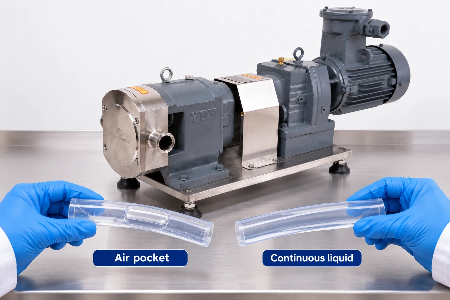
Choose detection from the failure mechanism
Possible measurements include liquid level, inlet pressure, flow, motor power, temperature, and seal support status. Each has limitations. Motor load can change with viscosity, speed, or discharge pressure. A temperature sensor may respond after damaging conditions begin. A flow switch can fail to detect the distinction between liquid and gas unless it is suitable for that purpose.
Use a combination appropriate to the consequence and required response. Define what the instrument measures, how quickly it detects loss of supply, and what happens if it fails. A sensor installed in a convenient location may not represent the vulnerable component. Verify the complete detection-to-stop chain rather than checking the instrument alone.
| Protection input | Useful evidence | Limitation to address |
|---|---|---|
| Feed tank level | Remaining supply and drawdown trend | Foam, vortexing and pipe inventory can mislead |
| Inlet pressure | Restriction or suction change | Pressure alone does not prove seal lubrication |
| Delivered flow | Loss of process transfer | Gas or bypass flow may affect interpretation |
| Motor power | Change from an established operating signature | Viscosity, speed and pressure also change power |
| Seal temperature | Thermal departure near a monitored location | Sensor response may lag the damaging event |
| Seal support status | Availability of required flush or cooling | Correct pressure, flow and fluid identity still matter |
The table identifies design questions rather than mandatory protection devices. Select setpoints and response times from the equipment instructions and a competent risk assessment. Do not assign an arbitrary delay simply to avoid nuisance trips.
Write a start sequence that proves readiness
Before starting, confirm the approved valve arrangement, available liquid, inlet path, discharge path, and seal support condition. A positive-displacement pump also requires suitable overpressure protection; dry-run protection does not address a blocked discharge. Review the pump speed guide when speed changes affect filling and drive load.
Do not assume that priming is harmless. Follow the permitted priming method and define when the attempt must stop. If liquid does not arrive, investigate the cause under the appropriate isolation procedure. Repeated short attempts can accumulate heat even when no single attempt seems long. Keep the total sequence within the manufacturer’s verified limits.
The US Department of Energy pumping-system sourcebook supports evaluating the pump as part of a complete hydraulic system. It does not replace the exact seal and pump instructions, especially for unusual product properties or cleaning conditions.
Loss-of-liquid protection and blocked-discharge protection address different conditions. Review the pressure-relief route and its operating basis separately before commissioning the complete pumping system.
Coordinate shutdown with draining and cleaning
A pump can be protected during production and exposed during cleaning because the control system uses a different sequence. Identify when the cleaning liquid reaches the pump, how the circuit drains, and whether a final air blow or purge is permitted. Confirm that the pump is not expected to run through a dry part of the cycle unless its documented configuration allows it.
If the process changes direction, verify the implications for connections, seals, support systems, and protection. Do not assume every bypass or pressure device works in both directions. Record the approved operating modes and the required interlocks for each one. A manually selected maintenance mode must not silently remove essential protection during production.
Respond to a suspected dry-running event
Stop using the approved sequence and preserve the operating evidence. Record duration estimates, speed, temperature, product, tank level, alarms, and operator actions. Avoid restarting simply because the casing feels cool or the supply has returned. Internal components may have experienced a different temperature and may require inspection or replacement according to the manufacturer.
Maintenance requires effective isolation of electrical, mechanical, pressure, thermal, and chemical energy. The OSHA hazardous-energy guidance provides the general framework. Do not loosen a fitting to check for liquid while pressure can remain trapped. Follow the site’s decontamination and depressurization procedure before opening the equipment.
After inspection, verify seal integrity, rotation freedom where the approved procedure permits that check, support-system condition, and the cause of lost supply. Evaluate product contamination if component damage could have introduced debris or if overheated product remained in the pump. The release decision belongs to the site’s quality and engineering procedures.
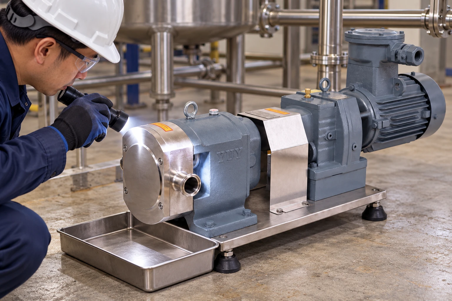
Prove that protection works under controlled conditions
A protection test should simulate the relevant signal or use another approved method without deliberately damaging the pump. Confirm that the alarm, trip, stop time, and restart permission behave as documented. A screen indication that changes color is not proof that the drive stopped or that the required valve action occurred.
Retain the test method, configuration, measured response, and any limitations. Recheck after changing instruments, control logic, pump speed range, seal arrangement, or supply geometry. If nuisance trips occur, investigate the signal and operating envelope before increasing delays or bypassing the function. A frequently bypassed protection arrangement is a sign that the design or procedure needs review.
Request the right information when purchasing
For a high-viscosity rotary lobe pump, provide the product properties, supply arrangement, operating temperature, expected interruptions, cleaning sequence, and required protection evidence. Ask explicitly whether the proposed configuration permits any dry operation and under which documented conditions.
Request a configuration-specific operating manual, seal support requirements, alarm and trip recommendations, and maintenance response after loss of liquid. Product photographs establish the visible equipment arrangement, not dry-running permission. The rotor-pump selection guide provides the broader duty information to include in that discussion.
Keep a clear record of every approved operating mode. An instruction for a water test should not be carried into hot, viscous, abrasive, or chemically aggressive service without a documented review.
Further learning: positive-displacement pumping principles
NPTEL explains positive-displacement pump types and operating principles. Use this university lecture as background for understanding displacement, flow and system resistance. It does not establish a dry-running allowance for a rotary lobe pump; the installed seal, fluid and manufacturer limits still control the operating decision.
Watch W3L5_Positive displacement pump by NPTEL-NOC IITM
FAQ
Does self-priming mean a rotary lobe pump can run dry?
No. Self-priming capability and permitted dry operation are separate claims. Confirm the exact configuration, procedure, and limits in the manufacturer’s documentation.
Is low motor current a reliable dry-run signal?
It can be one useful input after validation, but speed, viscosity, pressure, and mechanical condition also affect current or power. Verify the signal against the actual failure scenario.
Can the pump restart as soon as liquid returns?
Only after the approved checks. Investigate the loss of supply and assess seal or product damage before restoring operation under the documented restart procedure.


