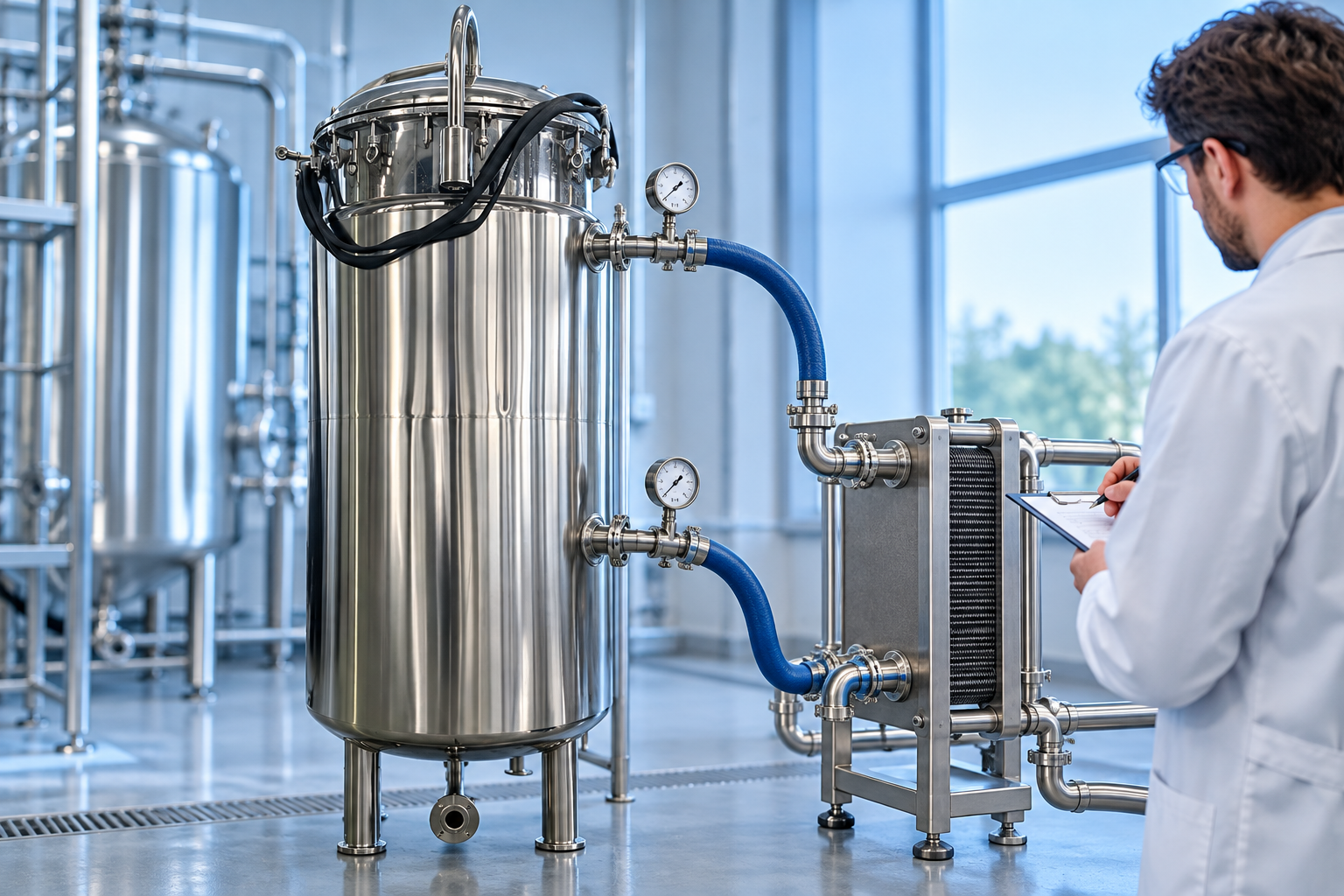
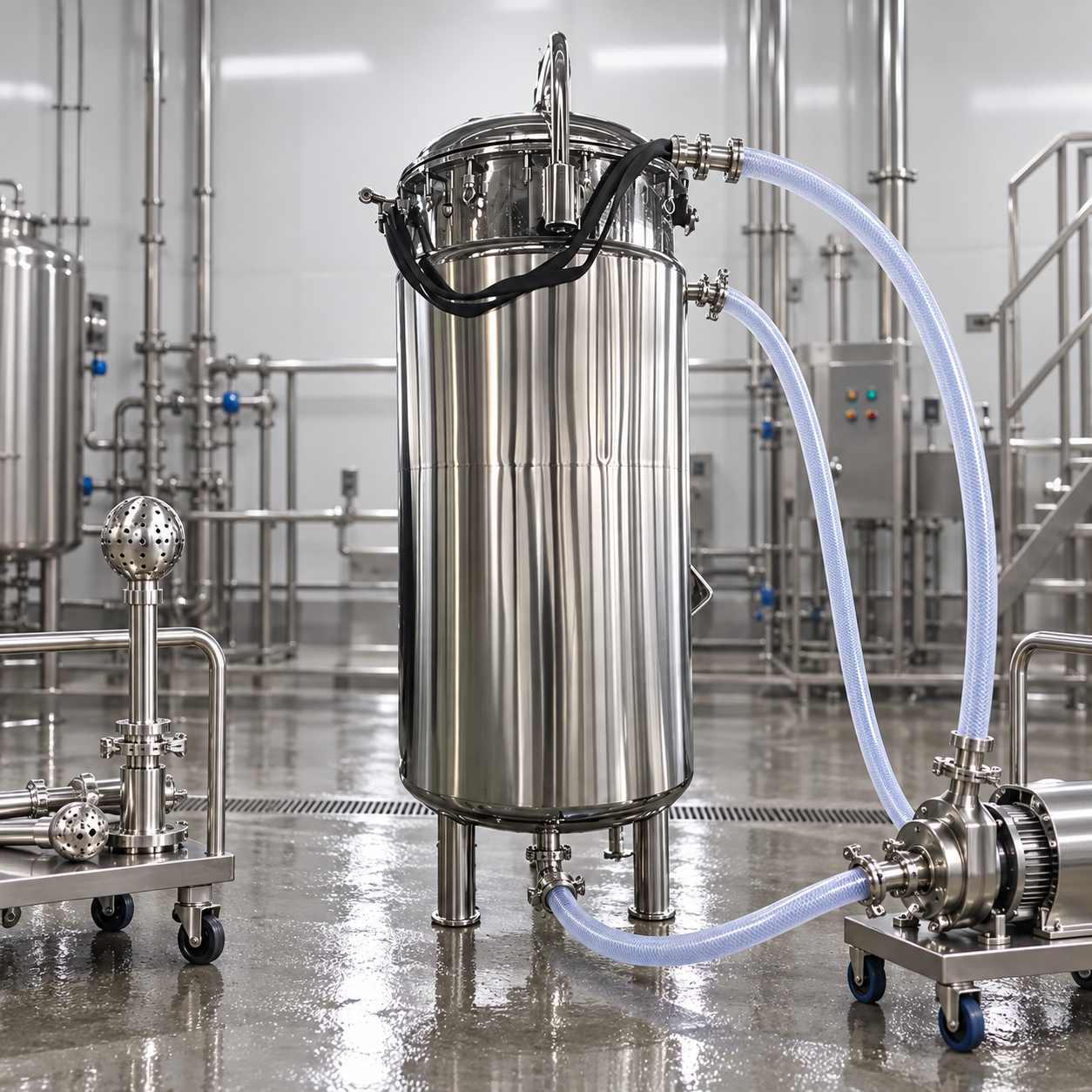
Stainless steel tank insulation is a complete thermal and moisture-control system, not simply a layer wrapped around a vessel. Buyers must define the process temperature range, ambient humidity and weather, allowable heat gain or loss, surface-temperature goal, cleaning environment, fire and hygiene requirements, and inspection strategy. The design then selects insulation material and thickness, vapor control, stainless or other outer cladding, attachment details, penetrations, removable sections, and drainage. Poor details can admit water, hide corrosion, compress insulation, create thermal bridges, or obstruct nozzles and maintenance even when the nominal insulation material is suitable.
Define the thermal duty before choosing material
Clarify whether the tank must keep product hot, keep it cold, prevent freezing, limit condensation, protect personnel, stabilize a batch, or reduce energy use. Record minimum and maximum product temperature, ambient design range, wind, solar exposure, humidity, operating cycle, standby time, fill pattern, and acceptable temperature change. A tank that is hot continuously has a different moisture and expansion profile from one that cycles between cleaning temperature and cold product.
Heat-transfer calculations should include shell, roof or head, bottom, nozzles, supports, manways, and other thermal bridges. Insulation thickness depends on thermal conductivity at the mean service temperature, geometry, surface coefficient, emissivity, and project objective. Do not copy a thickness from a nearby pipe or another plant. The U.S. Department of Energy’s process heat overview explains the importance of reliable heat transfer and controls in industrial systems; a project calculation converts that principle into tank-specific requirements.
Hot and cold service need different moisture strategies
For hot service, insulation reduces heat loss and external surface temperature, but cladding still needs weather resistance and room for thermal movement. For cold service, warm humid air can drive water vapor toward the cold surface. A continuous vapor-control layer, sealed joints, compatible mastics, and carefully detailed penetrations are essential. One small opening around a nozzle or support can allow moisture into a large area.
Condensation may occur on the outer cladding if its surface falls below the local dew point, or within the system if vapor reaches a cold layer. State the design ambient temperature and relative humidity rather than asking merely for “anti-condensation insulation.” For outdoor tanks, add rain, wind-driven water, ultraviolet exposure, and freeze-thaw cycling. For indoor hygienic spaces, include washdown pressure, cleaning chemicals, and the need to prevent water behind cladding.
Select insulation by service conditions
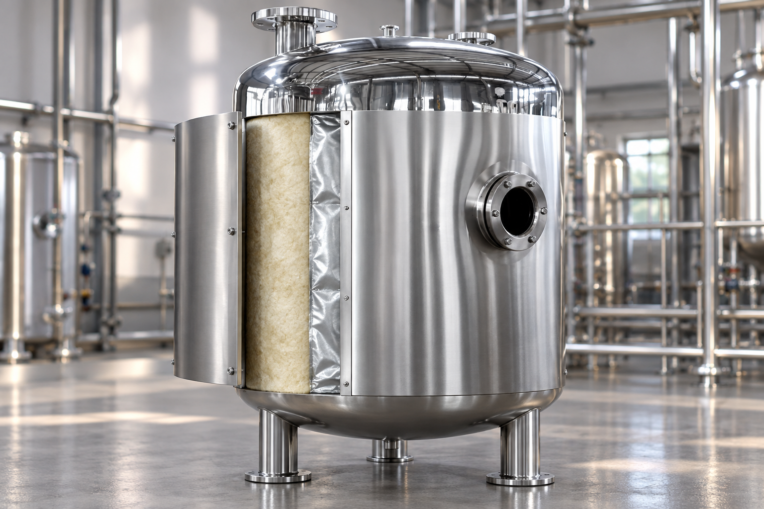
Mineral wool, fiberglass, cellular glass, calcium silicate, aerogel blankets, and closed-cell foams each have different conductivity, temperature limits, compressive strength, combustibility, water behavior, chemical compatibility, and installation requirements. The product data must cover the actual temperature range and orientation. A material that performs well dry may lose effectiveness or create corrosion risk when wet. A high compressive strength may matter beneath support rings or removable panels, while flexibility may matter on curved shells.
The DOE’s steam system sourcebook identifies thermal conductivity, strength, abrasion resistance, workability, and resistance to water absorption as important insulation properties. Although its examples emphasize steam systems, those selection categories are useful for tanks. Verify current manufacturer data and project fire requirements instead of relying on generic material names.
Design cladding as a weather and hygiene barrier
Outer cladding protects insulation from weather, impact, washdown, and contamination. Stainless steel is often selected for durability and hygienic appearance, but grade, thickness, seam orientation, fasteners, bands, expansion joints, and finish still need definition. Arrange overlaps to shed water. Seal penetrations without creating pockets, and protect lower terminations from standing water and mechanical damage. A bright jacket is not evidence that the insulation beneath is dry.
Where cladding contacts dissimilar metal, evaluate galvanic and crevice conditions. Avoid sharp edges and exposed fasteners in personnel areas. For food or pharmaceutical surroundings, define cleanability of the external jacket without claiming that insulation makes the product-contact surface hygienic. Product-contact finish remains a separate requirement; see the hygienic tank surface-finish guide.
Prevent corrosion under insulation
Stainless steel can suffer localized corrosion when moisture and contaminants remain trapped under insulation. Risk depends on alloy, temperature cycling, chlorides, water ingress, coating or barrier system, geometry, and inspection access. Keep chloride-bearing materials and wash chemicals out of the system, use compatible components, design water-shedding details, and define how wet insulation will be detected and replaced. Do not assume stainless cladding protects the underlying vessel if seams leak.
Specify surface preparation and any protective coating based on the corrosion-control plan. Record materials used in contact with the shell. Pay particular attention to nozzles, manways, support rings, nameplates, clips, lower heads, roof transitions, and areas under removable blankets. These discontinuities are common water-entry or thermal-bridge locations. A small inspection port can help only if it is sealed during service and located from a risk-based inspection plan.
Detail supports and attachments without crushing insulation
Insulation supports, rings, pins, bands, and cladding attachments must carry their loads while allowing tank expansion. Excessive band tension can crush fibrous insulation and reduce thickness. Metal paths through insulation increase heat transfer. On a vertical tank, support rings may be needed to prevent sagging; on heads and roofs, segment layout must resist sliding and water entry. Attachment welding should be completed and inspected before surface treatment and insulation.
Tank legs, saddles, skirts, and anchors interrupt the thermal envelope. Decide whether they are insulated and how inspection remains possible. Load-bearing insulation must have verified strength; ordinary blanket should not be placed beneath a structural bearing point. If load cells are installed, insulation and cladding must not bridge the moving assembly. Coordinate all details with the support design described in the tank foundation and support guide.
Insulation system selection table
| Service question | Design response | Acceptance evidence |
|---|---|---|
| Required heat loss or gain limit | Calculate material and thickness at actual temperatures | Thermal calculation with stated assumptions |
| Cold surface below dew point | Continuous vapor control and sealed penetrations | Detail drawings and installation inspection |
| Outdoor weather or washdown | Water-shedding cladding, sealed joints, drainage | Cladding material and seam inspection |
| Fire or personnel exposure | Applicable material rating and surface-temperature target | Product data and project code review |
| Frequent nozzle access | Removable, replaceable insulated covers | Demonstrated removal and refit |
| Corrosion-under-insulation risk | Moisture control, compatible materials, inspection access | Material certificates and inspection plan |
Plan removable sections and maintenance access
Manways, valves, instruments, sample points, nameplates, lifting lugs, grounding points, and inspection locations may need removable insulated covers. Covers should refit without gaps, maintain vapor or weather continuity, and withstand repeated handling. Store them properly during maintenance; damaged or omitted covers can dominate heat loss and admit water. The DOE sourcebook notes the value of removable insulation on components that require access.
Provide clearance for calibration, bolt removal, gasket replacement, and cleaning. Do not bury a leak-detection port, overflow, relief device, or mandatory nameplate. Where hot surfaces present burn risk during cover removal, define isolation and cool-down procedure. Maintenance drawings should show layer sequence and approved repair materials so field patches do not introduce incompatible sealants or wet absorbent material.
Factory inspection and site installation
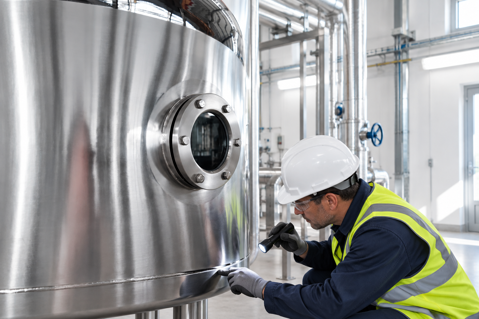
Before insulation, accept shell fabrication, leak testing, passivation or coating, attachments, and required surface inspection. Photograph hidden areas and record dry condition. Inspect insulation lot identification, thickness, fit, joint staggering, vapor-control continuity, support spacing, cladding overlaps, sealants, penetrations, and removable covers. A final visual check cannot reveal every concealed gap, so use hold points while layers remain visible.
If insulation is shipped installed, protect it from rain, impact, and transport damage. If installed on site, define storage conditions so material stays dry. After installation, verify nozzle access, instruments, grounding, supports, drains, and labels. Thermal imaging after stable operation can identify gross hot or cold spots, but interpretation depends on emissivity and operating conditions; it complements, not replaces, construction inspection.
Operating inspection and repair
Periodically inspect dents, open seams, failed sealant, loose bands, discoloration, cold spots, hot spots, condensation, ice, biological growth, and water at lower edges. Look closely after maintenance, severe weather, or washdown. If water ingress is suspected, open the system under an approved plan and determine the extent; drying only the outer surface does not restore saturated insulation.
Replace damaged material with compatible components and restore every layer, including vapor control and cladding. Investigate the entry path instead of patching only the lowest drip point. Record repaired areas for follow-up. When process temperature or product changes, revisit the original thermal and corrosion assumptions rather than treating insulation as a permanent unchanged accessory.
Product and RFQ connection
The 1,000 L alcohol receiving tank provides the vertical stainless form used as the image reference. The illustrated insulation is conceptual and not a claim that every standard tank includes that layer system. Buyers should provide thermal duty, environment, cleaning, fire, cladding, and inspection requirements for the ordered vessel. The storage tank range helps establish geometry before the insulation contractor completes a takeoff.
Request a thermal calculation, materials schedule, layer and seam drawings, nozzle and support details, attachment map, vapor-control specification, removable-cover list, installation procedure, quality plan, and repair materials. State who supplies heat tracing and who guarantees continuity at interfaces. This prevents gaps between tank, insulation, electrical, and site contractors.
Educational video
This NPTEL/IIT Kharagpur lecture explains critical insulation thickness, an important heat-transfer concept. Tank insulation still requires a project calculation that includes geometry, temperatures, moisture, safety, and constructability.

View the NPTEL insulation lecture on YouTube.
Frequently asked questions
Is stainless steel cladding itself insulation?
No. Cladding protects the insulation system. Thermal performance comes primarily from the specified insulation layers and their dry, continuous installation.
Why is a vapor barrier important on a cold tank?
It limits humid air and water vapor from reaching cold layers where condensation can wet insulation, reduce performance, and promote corrosion.
Can insulation hide tank leaks or corrosion?
Yes. Design removable access and a risk-based inspection plan, and investigate water ingress or staining promptly rather than relying only on the visible cladding.