

The shell side vs tube side fluid decision assigns one stream to the tubes and the other to the surrounding shell of a heat exchanger. Make the choice by comparing pressure, corrosion, fouling, viscosity, phase behaviour, cleaning access, and the consequences of leakage. Higher-pressure or corrosive service often favours the tube side, but these are starting preferences rather than universal rules. The final allocation must satisfy both streams’ thermal, hydraulic, mechanical, and maintenance requirements. It should be recorded on the approved datasheet and drawing so installation and testing follow the same design basis.
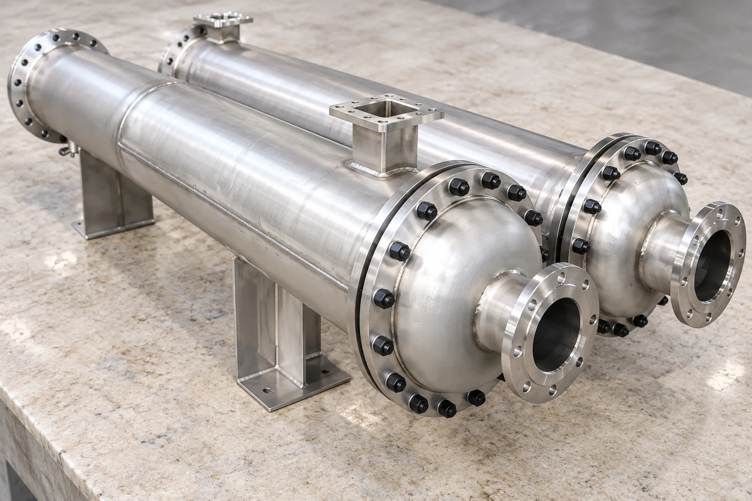
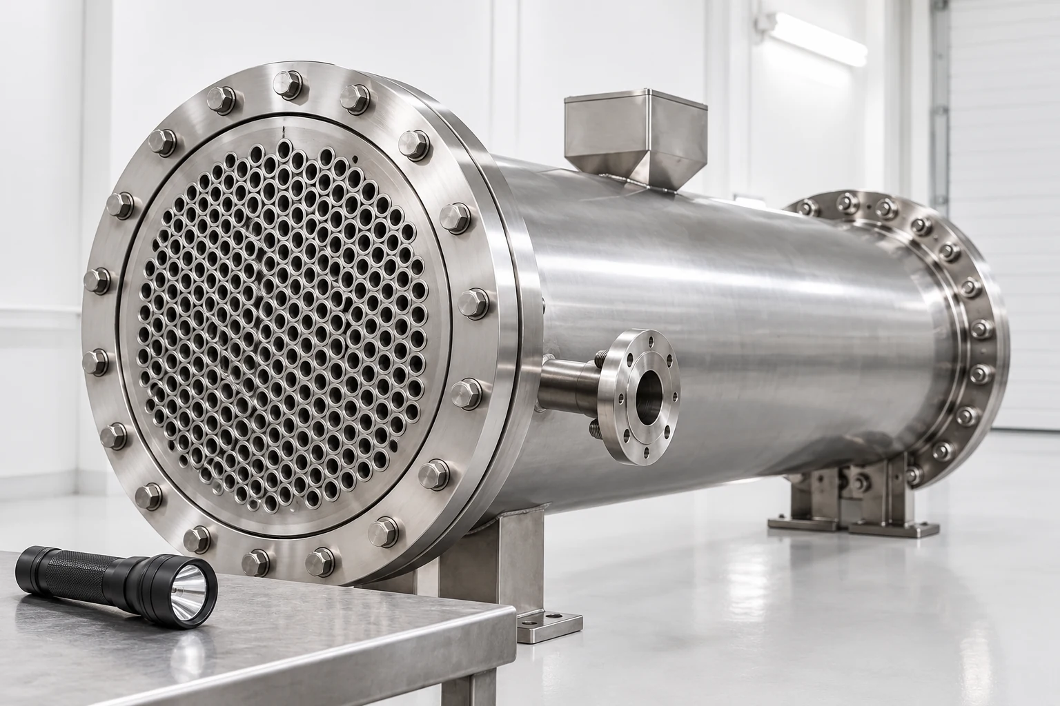
Use this guide to structure a supplier discussion, rather than choose the side from a photograph. Our industrial tubular exchanger guide covers the broader selection process. The fixed-tube-sheet exchanger is equipment context; its visible connections do not establish suitability for a particular hazardous, corrosive, or high-pressure fluid.
Identify the two independent circuits
Tube-side fluid passes inside the tubes and associated channel passages. Shell-side fluid occupies the space outside the tubes within the shell. A tube wall and its joints separate the streams, while headers and partitions establish the intended pass arrangement. Ask for a marked drawing showing each nozzle, fluid, direction, and vent or drain requirement. A generic product name is insufficient to identify every connection on a delivered unit.
Create a side-by-side service description before ranking preferences. Include actual compositions, temperatures, pressure ranges, flow ranges, cleaning requirements, and foreseeable deviations. “Water” may mean treated cooling water, chlorinated water, demineralized water, or contaminated process water. “Oil” says little about viscosity at startup. Specific service information prevents a broad rule from becoming an unsupported purchasing decision.
Weigh pressure containment and material cost
Эт Society of Petroleum Engineers’ exchanger overview explains common allocation preferences for higher-pressure and corrosive streams. Confining high pressure to smaller tube passages can offer an economic advantage over pressurizing a large shell. Placing a corrosive stream inside tubes can also limit the extent of costly wetted materials. These preferences require review of the complete boundary, including channel heads, tube joints, nozzles, and gaskets.
Request comparable alternatives when both streams impose difficult conditions. The least expensive tube material alone does not identify the least expensive safe exchanger. Ask for the material basis, corrosion assessment, fabrication constraints, and inspection requirements on each side. Where composition or temperature is uncertain, record that uncertainty and seek a suitable materials review rather than accepting “stainless steel” as a complete compatibility statement.
Plan cleaning around the actual construction
A dirty stream is often assigned to accessible straight tubes because mechanical cleaning can be practical there. Confirm that both tube ends are accessible, the heads can be removed as intended, and the cleaning method fits the bore and deposit. A U-tube, narrow passage, or difficult head arrangement changes the maintenance plan. Do not infer straight-through brush access from the external shape of the shell.
Shell-side cleaning may require a removable bundle or a validated chemical procedure. A fixed-tube-sheet construction has different access from a floating-head arrangement. If a shell-side deposit must be removed mechanically, ask the supplier to demonstrate access on the proposed configuration before ordering. Our Руководство по обслуживанию упаковки helps turn that requirement into an installation and service-space discussion.
Consider viscosity over the operating range
Compare viscosity at the coldest startup condition and at normal operation. A design that is satisfactory after warmup may produce excessive resistance or poor distribution while cold. Ask whether the thermal and hydraulic calculations use the same property model and composition. Where a stream changes substantially along the exchanger, require an appropriate rating rather than a single unexplained viscosity value.
Shell-side placement may sometimes help a viscous stream through the available flow arrangement, but geometry and allowable pressure loss decide whether it works. It is not a guarantee of better performance. Review both allocation alternatives with the proposed baffles, tube count, pass arrangement, and nozzle sizes. Keep an explicit operating case for minimum flow, since meeting a nominal duty does not prove reliable turndown behaviour.
Treat boiling, condensing, and gas service separately
Phase-change service requires suitable distribution, drainage, vapour space, and pressure-loss analysis. Determine where condensate collects, how non-condensable gases leave, and whether local operating conditions introduce freezing, flashing, or unstable flow. A familiar preference for a particular side does not establish that the proposed orientation and venting are adequate. The phase-change calculation should identify the relevant regions and operating conditions.
For gas service, compare volumetric flow and available pressure rather than using liquid-service intuition. A modest pressure loss can matter greatly to a low-pressure gas circuit. Ask how density variation is handled and whether nozzle velocities and entrance losses are included. Provide startup, shutdown, and upset conditions when they affect the pressure relationship between the streams or the ability to drain equipment.
Compare allocation preferences explicitly
This table is a qualitative review tool, not a universal selection algorithm. The NPTEL shell-and-tube design lecture supplies thermal-design context; the allocation preferences above are discussed in the cited SPE overview. Resolve conflicting preferences through a documented comparison of actual designs rather than by counting how many rows favour one side.
| Service concern | Allocation to investigate | Evidence needed before approval |
|---|---|---|
| One stream has much higher pressure | Higher-pressure stream inside tubes | Complete pressure-boundary calculation and joint design |
| One stream requires costly wetted material | Corrosive stream inside tubes | Compatibility and all wetted-component materials |
| Deposits need straight mechanical access | Dirty stream in accessible straight tubes | Head removal, bore access, and cleaning method |
| Viscosity varies strongly with temperature | Rate both alternatives over the range | Property basis, distribution, and pressure losses |
| Phase change occurs | Arrangement suited to drainage and distribution | Orientation, vents, phase regions, and off-design cases |
| Leakage has serious consequences | Evaluate containment and detection requirements | Hazard review and response to either leakage direction |
Evaluate leakage consequences on both sides
The higher-pressure stream may enter the lower-pressure circuit if the separating boundary fails, but normal operating pressure is not the only relevant state. Consider shutdown, cleaning, isolation, and a loss of utility pressure. Do not use fluid allocation as the sole safeguard against contamination or overpressure. Have the responsible engineer review credible failure cases and the measures required by the applicable project rules.
Discuss whether contamination would damage product, create a chemical hazard, or affect a downstream system. Ask how leakage would be detected, what the operator would do, and which equipment must tolerate the resulting condition. The HSE pressure-system introduction provides general safety context. It does not determine the project relief design or confirm compliance for a specific exchanger.
Account for thermal expansion and mechanical access
Fluid allocation affects the temperature conditions experienced by the shell, tubes, and joints. The selected construction must accommodate the expected temperature differences and transients. Identify rapid startup or cleaning temperature changes rather than presenting only a steady operating case. Request a mechanical review appropriate to the equipment construction and intended service. Moving a stream to the opposite side can alter that review even when the nominal heat duty is unchanged.
Service access also includes channel-head removal, nozzle disconnection, lifting space, drainage, and inspection. Ask the maintenance team to review the proposal with the installation drawing. A thermally acceptable allocation can still be impractical if the dirty side cannot be serviced within the available space. Record access dimensions as requirements, but obtain actual values from the approved equipment design rather than generic rules.
Keep allocation distinct from flow direction
Putting a stream in the shell does not by itself make the exchanger counterflow, and putting it in the tubes does not establish parallel flow. Pass partitions, baffles, and piping determine the thermal arrangement. The LearnChemE educational video below helps connect inlet conditions and thermal performance. It is thermal background, not evidence for a materials decision, pressure rating, or safe allocation of hazardous streams.
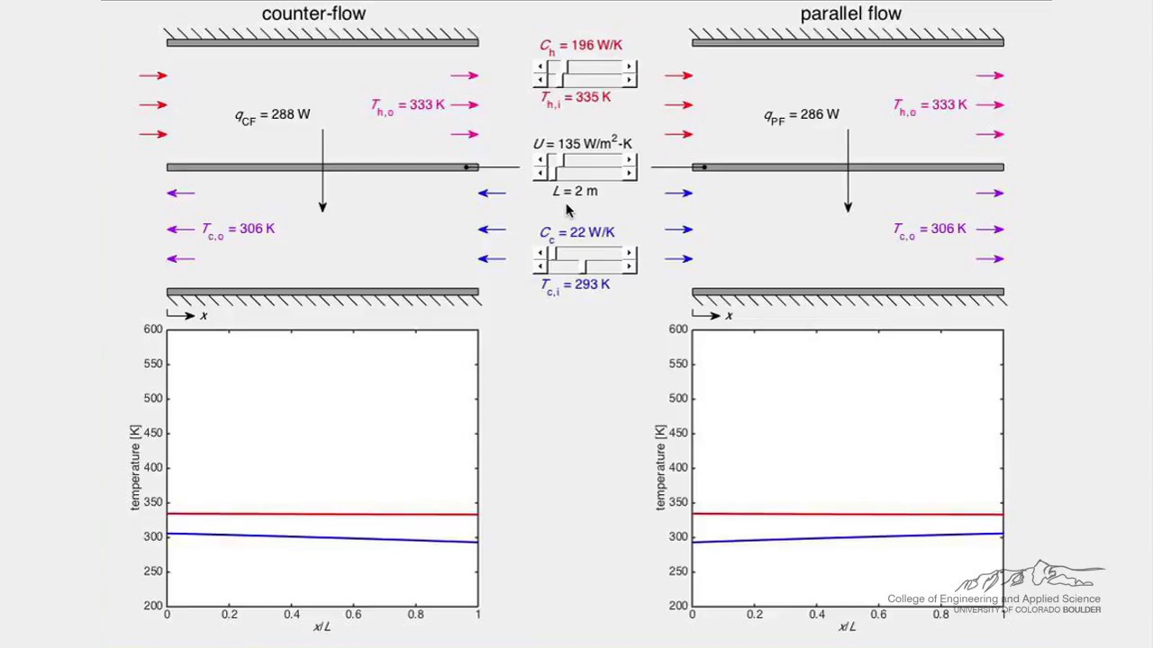
Посмотрите видео «Теплообменник (симуляция)» от LearnChemE
When reviewing a proposal, request a flow sketch together with the side assignment. Check that the rating calculation uses that same arrangement and the quoted side-specific pressure allowances. If the supplier changes the pass arrangement during optimization, require an updated drawing and operating table. This prevents an early allocation note from being treated as final after the geometry has changed.
Review a practical allocation conflict
Consider a hypothetical viscous process stream that also fouls, paired with a clean utility stream at higher pressure. Straight-tube access may favour putting the process stream inside the tubes, while pressure containment may favour putting the utility there. The useful response is to compare two proposed designs, not to announce that one generic preference overrides the other. Ask for duty, both-side losses, material requirements, access, and lifecycle maintenance consequences for each alternative.
If the dirty stream goes into the shell, confirm a workable deposit-removal method. If it goes into the tubes, confirm that the tube-side hydraulic limit is achievable over startup and normal operation. Review the consequences of leakage under either allocation. These comparisons make the tradeoff visible and identify which additional information could change the decision. The example does not represent a supplied YIYI installation.
Document the decision before manufacture
The inquiry should include both fluid specifications, flow and temperature ranges, operating and design pressures, allowable losses, fouling expectations, cleaning method, and leakage consequences. State any mandatory side assignment and explain its reason. If the assignment is open, request the supplier’s recommendation with alternatives and exclusions. Link the agreed outcome to the final datasheet and drawing revision.
Before approval, check that nozzle labels, material schedules, tests, and installation instructions use the same stream names. Retain the comparison and unresolved conditions in the procurement record. For complementary deposit planning, see our heat-exchanger fouling guide. Send YIYI the service data and maintenance constraints so the next discussion can evaluate a specific configuration instead of a broad product category.
Часто задаваемые вопросы
Must the corrosive fluid always be in the tubes?
No. Tube-side placement is a common economic starting point, but compatibility, joints, cleaning, hydraulic limits, and leakage consequences may change the decision. Evaluate the complete wetted boundary.
Is cooling water always assigned to the tube side?
No. Water quality, deposits, pressure, cleaning access, and the other stream’s requirements matter. Specify the actual water composition and treatment condition rather than relying on its name.
Does fluid allocation establish counterflow?
No. Allocation identifies which circuit carries each stream. Flow direction and mixing depend on the pass arrangement, baffles, and connected piping, which need their own drawing and rating basis.
What should settle conflicting allocation preferences?
Compare actual alternative designs against duty, both-side losses, materials, maintenance, and failure consequences. Record the responsible engineering decision and the conditions on which it depends.


