

Rotary lobe pump cavitation occurs when local liquid pressure falls low enough for vapour cavities to form and subsequently collapse as pressure recovers. The practical warning signs can include changing noise, vibration, unstable delivery and damage, but none of these symptoms alone proves cavitation. Begin with the actual suction conditions, liquid temperature, pump speed and operating history. Distinguish vapour formation from entrained air, incomplete filling and mechanical faults before changing equipment. The correct remedy often concerns the supply vessel or inlet piping rather than the motor or the pump casing.
Separate cavitation from other noisy-pump problems
A rotary lobe pump carries liquid in moving pockets between the rotors and casing. If the supply cannot fill those pockets under the operating conditions, delivery can deteriorate. Vapour formation is one possible mechanism; air entering the system is another. Mechanical contact, bearing wear, misalignment and a damaged coupling can also produce noise. Treat the sound as a reason to investigate rather than a diagnosis.
Ask when the symptom appears. A problem limited to cold startup points toward a different investigation from one that begins near the end of every tank discharge. Noise following a recipe change may relate to fluid properties. Noise after maintenance may relate to assembly, clearance or alignment. Collect that history before dismantling the pump, provided continued operation is safe under the site’s procedure.
For general suction concepts, the NPTEL discussion of pump characteristics and NPSH explains why inlet pressure must be considered relative to liquid vapour pressure. The lesson uses centrifugal-pump examples; the selected lobe pump still requires its own supplier suction criteria.
Measure the conditions at the inlet
Record inlet pressure, liquid temperature, actual rotational speed, discharge pressure and delivered flow at the time of the symptom. Include vessel level and the status of inlet valves or strainers. Measurements taken during a later stable period may conceal the operating condition that caused the event. If possible, trend the variables together so a change in suction pressure can be related to a falling tank level or increasing speed.
Identify pressure units and reference. An inlet reading described only as a negative number is incomplete: it must specify whether the instrument measures gauge pressure, vacuum or absolute pressure. Record the location of the tapping and check for blocked instrument connections. A reading upstream of a long restrictive hose is not the pressure at the pump connection.
Confirm that the instruments are appropriate for the material. A product containing solids can block a small pressure connection; a pulsating signal can appear different with different damping settings. Review the measurement arrangement before attributing a noisy or flat trace to pump behaviour.
Check the supply vessel and suction route
Start with the simplest questions. Is the correct valve fully open? Is a strainer clean? Has a temporary hose been substituted for a larger permanent line? Is the vessel vent functioning as intended? Does the inlet remain covered at the lowest operating level? Each question should be checked against the approved arrangement, not answered from assumptions about normal operation.
Review suction-line diameter, length, elbows, changes in section and any restrictive instruments. The Department of Energy pumping-system sourcebook supports examining the pump and connected system together. Its guidance is a starting point for reviewing losses; it does not provide a universal suction-line size for viscous product transfer.
Do not remove a strainer or bypass a protective component merely to reduce resistance. Its function may protect the pump or the downstream process. Compare the actual loss with the original design allowance, then decide whether cleaning, a larger appropriate component or another engineered change is required. Retain the reason for the component in the modification review.
Review viscosity, temperature and speed together
Cold viscous product can increase inlet resistance and slow filling. Heating may reduce viscosity, but it can also increase vapour pressure and change seal or product limits. There is therefore no general rule that warmer fluid always cures a suction problem. Use a measured or supplied viscosity-temperature relationship and review the permitted process temperature before changing the recipe.
Pump speed changes the rate at which cavities need to fill. Reducing speed can be a useful diagnostic action when permitted, but the resulting lower noise does not by itself identify the mechanism. Compare flow, inlet pressure and product condition at the new operating point. A controlled trial should answer a specific question, such as whether inlet restriction dominates the symptom.
Ask the supplier for the acceptable speed and suction envelope at the specified viscosity, flow and temperature. A catalogue maximum speed is not necessarily suitable for the duty. Avoid selecting a larger motor or increasing speed to overcome reduced delivery until the inlet condition and pressure-protection arrangement have been reviewed.
Use the symptoms to guide checks
| Observed pattern | Possible explanation to investigate | Useful confirming evidence |
|---|---|---|
| Noise increases as the vessel empties | Reduced static supply head or inlet uncovering | Level and inlet-pressure trend during discharge |
| Problem starts with colder product | Increased inlet resistance or incomplete filling | Temperature, viscosity information and speed trial |
| Bubbles appear after a connection is disturbed | Air entry at a seal, hose or fitting | Approved leak inspection and connection review |
| Delivery drops after a strainer loads | Increased suction restriction | Differential pressure and inspection findings |
| Noise remains with stable suction conditions | Mechanical or discharge-side issue | Alignment, bearing, clearance and pressure records |
| Symptom appears only at higher speed | Insufficient filling margin at that duty | Supplier envelope and matched operating measurements |
These are investigation routes, not guaranteed diagnoses. Several mechanisms can occur together. For example, a restrictive inlet and air leakage can both worsen as suction pressure falls. Document the evidence for each conclusion and avoid replacing an entire pump based on one observation.
Distinguish air ingress from vapour formation
Air may enter through a poorly sealed connection even when the joint does not visibly leak liquid outward. Air can also arrive from a vortex, foam or deliberate gas addition upstream. Review the vessel outlet and the process sequence alongside joints, hoses and seals. Do not assume that all bubbles were generated inside the pump.
A change in temperature and pressure can influence vapour formation, while a damaged connection may admit air independent of the liquid’s vapour pressure. Use the combined operating evidence to narrow the cause. If a viewing section is used for diagnosis, its pressure, material compatibility and safe installation must be confirmed first.
Check whether the flow meter remains valid during two-phase service. A meter calibrated for a full liquid stream may misrepresent the amount of product transferred when bubbles are present. Compare measurements with a suitable tank balance or another approved reference method before declaring that the pump’s displacement has changed.
Make corrections without introducing a new hazard
Changes can include restoring valve position, cleaning a restriction, improving the supply arrangement, reducing approved speed or selecting equipment suited to the inlet duty. The choice should follow the established cause. Increasing vessel pressure, heating product or modifying relief settings are process changes requiring a competent engineering review; they are not routine troubleshooting shortcuts.
Treat blocked-discharge protection as a separate question. A positive-displacement pump can develop excessive pressure if its outlet is obstructed. Fixing suction performance does not remove that risk. Verify the installed protective arrangement and permitted settings against the system design and supplier documentation.
Эт Руководство по системам давления в системах HSE provides a useful safety reference for managing pressure equipment. Apply the site’s applicable legal and engineering requirements. Isolate, depressurise and secure the equipment under the approved procedure before opening it; an apparently quiet pump can still contain trapped pressure and hazardous material.
Inspect damage and prove the repair
When inspection is justified, preserve photographs and identify the exact locations of marks, erosion or wear. Avoid labelling every pit as cavitation damage: corrosion, abrasive particles and mechanical contact may produce different or overlapping evidence. Ask the supplier or a competent specialist to assess uncertain findings with the operating history available.
After correction, repeat an approved duty trial under the condition that previously caused the problem. Include low vessel level, startup temperature and the demanding route if they are part of normal service. Confirm flow, pressure, temperature, noise trend and seal condition. A quiet water trial alone does not validate a viscous production duty.
Record what changed and the operating limits that remain. If reduced speed is now required, update the operating instruction and control setting. If a maintenance restriction caused the event, define how it will be monitored. The repair is complete when the cause is supported, the required duty is demonstrated and the prevention measure is workable.
Equipment discussion and learning resources
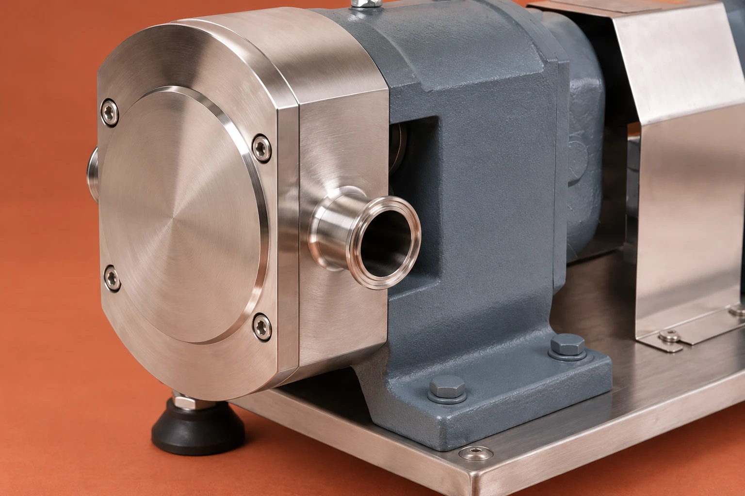
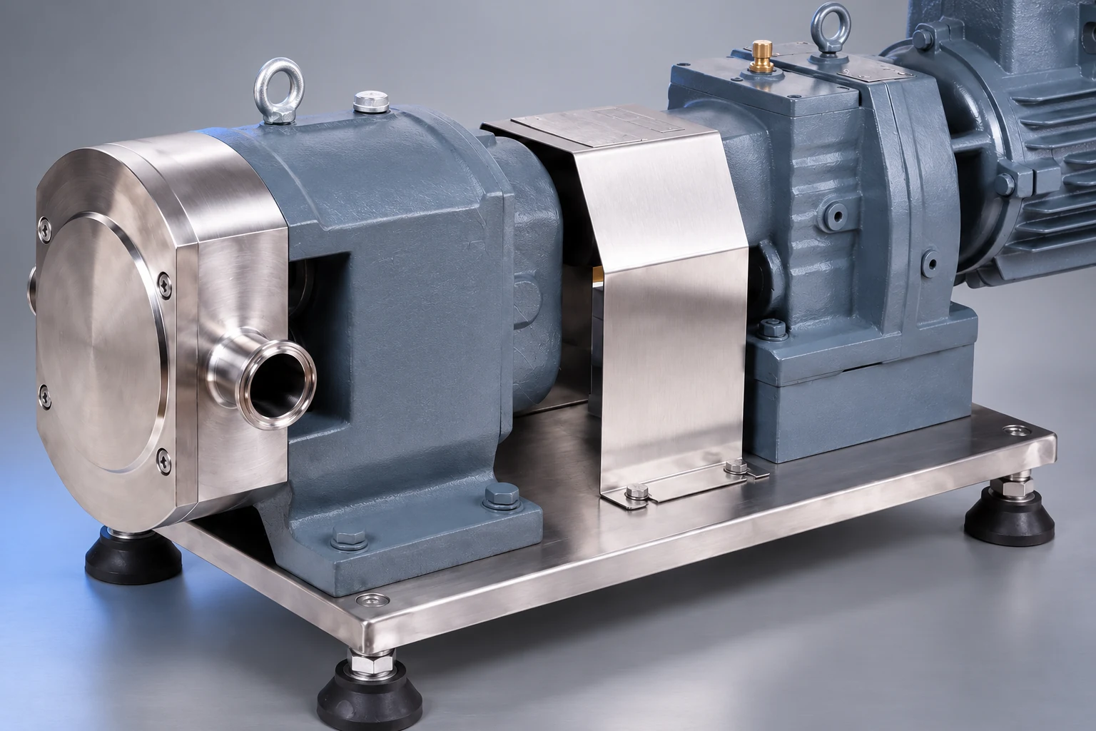
For a replacement or revised duty, send the measurements to the supplier of the rotary lobe transfer pump. Request selection data for the actual product, rather than assuming the photographed configuration has a particular suction capability.
Используйте rotor pump selection guide for the broader equipment enquiry, syrup tank viscosity planning for upstream fluid conditions, and пландуровка насадки резервуара для смешивания for the vessel outlet arrangement. These links address complementary decisions rather than replacing a cavitation investigation.
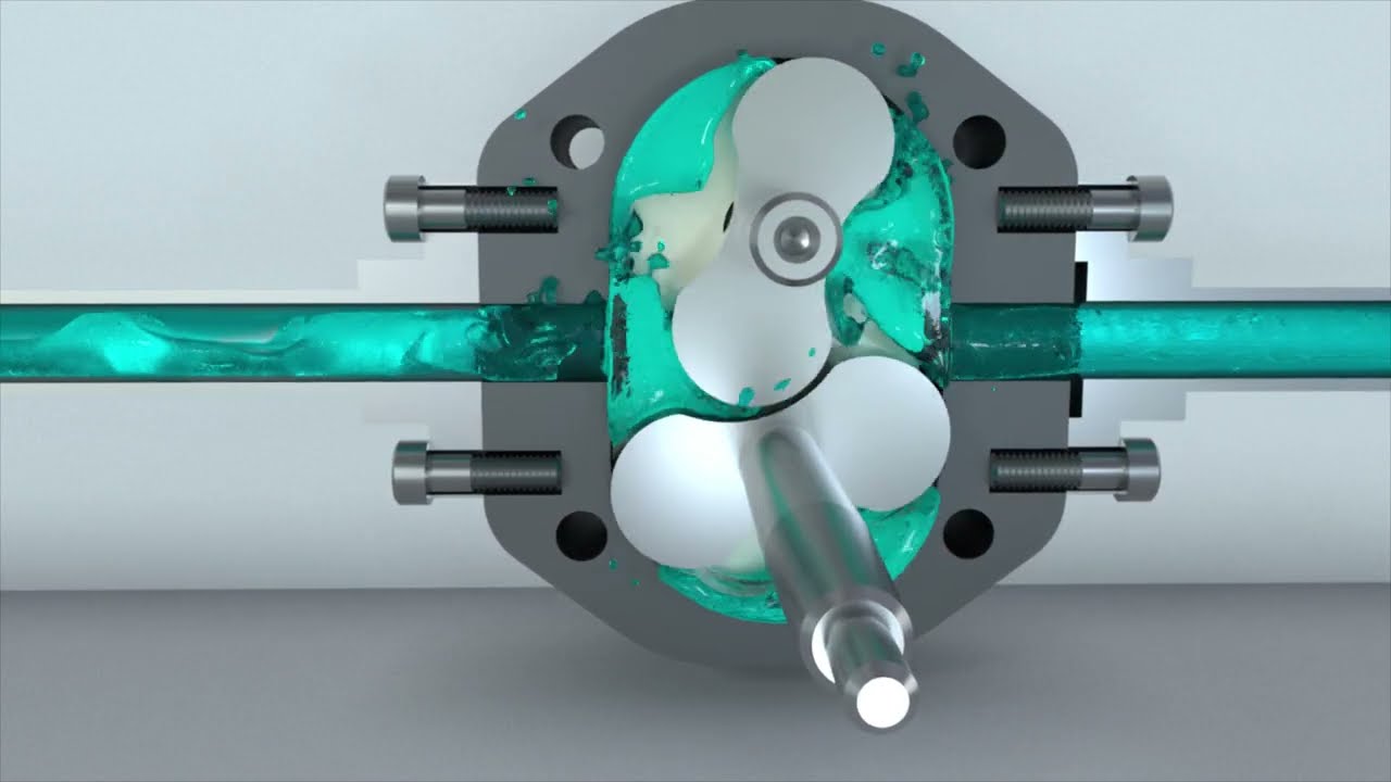
This independent educational animation shows how a rotary lobe pump carries fluid around its casing. It helps explain why filling the moving cavities matters, but it does not establish a suction limit for a specific pump.
Часто задаваемые вопросы
Does rattling noise prove rotary lobe pump cavitation?
No. Cavitation, entrained air, incomplete filling and mechanical faults can produce overlapping symptoms. Compare inlet pressure, temperature, speed, flow and operating history, then inspect under the approved procedure when necessary.
Can lowering speed solve the problem?
It may improve filling conditions and can be a useful controlled trial. Confirm that the resulting flow still meets the process duty and that supplier limits are respected. Use the result to identify the cause rather than treating quieter operation as complete proof.
What information should be sent to the pump supplier?
Send the suction and discharge layout, instrument locations, pressure reference, liquid temperature and viscosity, speed, vessel-level range, measured flow and the timing of the symptom. Include maintenance history and any photographs of damage for a duty-specific assessment.


