

The mixing tank minimum liquid level is the lowest operating level at which the installed agitator, process duty, and vessel remain within their verified limits. It depends on impeller position and geometry, fluid properties, shaft and seal requirements, heating arrangement, and the quality needed during drawdown. It cannot be set reliably as a fixed percentage of total tank capacity. A useful specification distinguishes the level needed to start mixing, the level at which mixing quality remains acceptable, and the level at which agitation must stop. Those limits may be different and should appear in the operating instructions.
Separate capacity from the operating envelope
A vessel can physically hold a small batch without being able to mix it adequately. The impeller may become partly exposed, circulation may collapse, or a powder addition may remain concentrated near the surface. Conversely, an impeller that remains covered may still lack the circulation needed to meet blend uniformity. Define the actual task: blending miscible liquids, suspending solids, transferring heat, or maintaining a sensitive emulsion.
The distinction complements working volume versus total volume. Capacity planning determines how much material fits with adequate headspace. A minimum-level review determines whether the process can operate at the lower end of that range. Buyers should ask for both values, the conditions supporting them, and any speed restrictions during filling and emptying.
Identify all level-dependent constraints
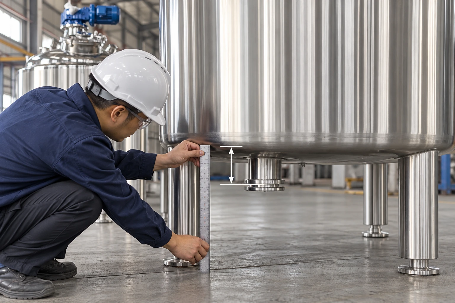
Begin with the vessel and agitator drawings. Locate every impeller relative to the bottom geometry and the level instrument datum. Confirm whether there are multiple impellers and what happens when an upper stage becomes uncovered. An exposed impeller can entrain air or generate an unstable load even while a lower stage still mixes liquid. Do not assume that operating fewer immersed stages is automatically permitted.
Review the seal and bearing arrangement with the supplier. Some designs depend on product lubrication, flushing, cooling, or liquid coverage; others have different operating requirements. A photograph does not establish those requirements. Separately review jacket zones, internal coils, electrical heating surfaces, and any parts that must remain wetted during operation. Agitator and heater interlocks may require different setpoints.
Avoid using a universal submergence rule
Published rules of thumb can help begin a discussion, but they do not qualify a particular installation. Impeller diameter, speed, liquid viscosity, surface tension, vessel diameter, and baffle arrangement all influence surface behavior. A low-viscosity water trial may show air drawdown that differs from the real product, while a viscous trial may show weak bulk circulation with little visible surface motion.
Use the supplier’s permitted operating envelope and verify the required process outcome. For a variable-speed mixing tank, ask which speeds are approved at each fill range. Reducing speed can limit surface disturbance but may allow settling or poor heat transfer. A low-level operating mode needs its own quality criteria rather than simply a slower motor setting.
Build a level-and-duty decision table
The following table is a planning tool. It does not prescribe safety setpoints or a specific vessel’s operating limits. Use the actual equipment documentation and process risk assessment to assign values and actions.
| Operating phase | Question to verify | Evidence needed before approval |
|---|---|---|
| Initial filling | Can the agitator start at this level? | Supplier start condition, fluid properties, drive response |
| Ingredient addition | Will the addition be dispersed without local excess? | Mixing trial, addition location, temperature and composition checks |
| Normal batch | Is every required quality attribute maintained? | Uniformity, solids or thermal measurements at representative points |
| Drawdown | Does circulation remain adequate as the level falls? | Controlled discharge trial and sample results |
| Low-level stop | What stops first: mixer, heater or transfer? | Reviewed sequence, instrument response and permitted equipment limits |
| Restart after interruption | Has material settled or changed viscosity? | Inspection and a separate restart procedure where required |
For measurements, use consistent units and documented calibration. Panduan kalibrasi NIST supports traceable measurement, while the SI unit reference helps prevent confusing height, volume, and mass. A calibrated level sensor still requires a valid conversion for the vessel shape.
Convert level into usable volume correctly
For a vertical cylindrical straight section, the volume change is approximately cross-sectional area multiplied by level change. This relationship changes in a conical or dished bottom. It also ignores internal displacement unless that is included. Use the tank calibration table or verified geometry rather than extending a straight-wall formula through the bottom head.
For illustration, a cylindrical section with an internal diameter of 1.0 metre has an area of approximately 0.785 square metres. A 0.10 metre level change within that section represents about 0.0785 cubic metres, or 78.5 litres, before displacement corrections. These are hypothetical geometric values, not a product capacity claim or a recommended minimum level. Applying the same conversion in a cone can give a materially wrong answer.
Record the instrument’s reference point. A level reading measured from a nozzle flange may differ from height above the lowest internal point. Clarify whether the stop point includes liquid motion, sensor uncertainty, and the level drop during control-system response. Do not choose a stop point solely from an average indication when the surface is fluctuating.
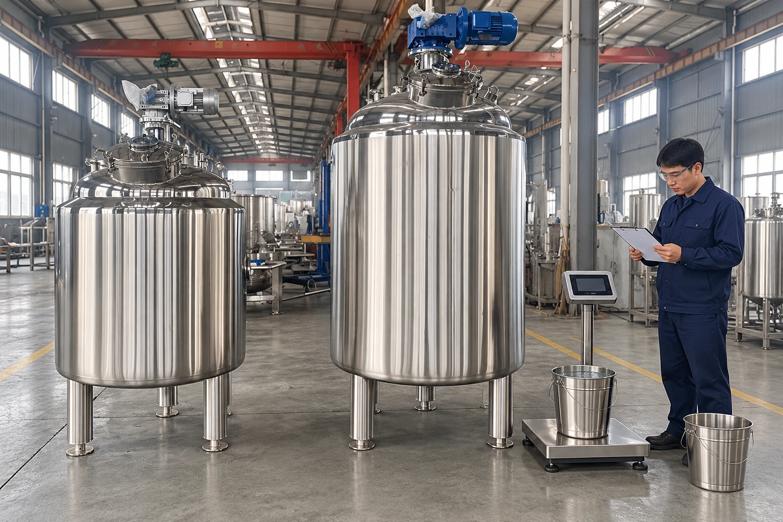
Where an approved water trial is suitable, a withdrawn quantity can be checked by weighing the same collection vessel before and after collection and converting net water mass with an appropriate density at the test temperature. Record the start and end levels and account for samples or retained liquid. This verifies a volume relationship; it does not establish acceptable agitation, heating or seal coverage at that level.
Test filling and drawdown as different cases
A batch can behave differently while filling than while emptying. During filling, concentrated liquid or powder may initially occupy a small volume. During drawdown, solids can accumulate at the bottom, the viscosity can change, or a floating layer can become more important. Test the actual sequence and discharge arrangement, not only a set of static levels.
At selected levels, record agitator speed, drive load, visible surface behavior through an approved viewing arrangement, sample uniformity, and relevant temperatures. Do not remove covers or bypass guards to watch the impeller. A transparent surrogate vessel can support development but does not establish the mechanical limits of the installed equipment. The final decision must combine process evidence with the equipment’s permitted use.
Itu vortex prevention guide addresses air entrainment and surface behavior. Tank bottom design explains how geometry affects circulation and drainage. Neither replaces a documented low-level trial for the actual batch range.
Where a tracer trial is appropriate, use the sampling and measurement-quality checks to separate instrument and sample effects from actual changes in circulation.
Design alarms and stops around verified limits
An alarm should give an operator a meaningful opportunity to act where operator response is part of the design. An automatic stop should account for instrument accuracy, signal delay, liquid discharge rate, and the consequence of continued operation. The appropriate arrangement depends on the hazard and applicable requirements; this article does not assign a safety integrity level or replace a control-system assessment.
Review what happens after a low-level trip. Should the transfer continue, stop, or switch to a permitted heel-removal step? Can the agitator restart automatically when liquid rises, or must an operator check the batch first? Unexpected restart and maintenance access require effective hazardous-energy controls. The OSHA hazardous-energy overview is a useful reference for that separate isolation requirement.
Handle difficult products and interruptions
Settling slurries may need an earlier stop criterion if suspension is lost during drawdown. A small remaining heel can contain a disproportionately high solids concentration. High-viscosity products may stop circulating even though the impeller remains fully immersed. Foam can make a level instrument indicate material that provides little useful liquid coverage. Identify these cases explicitly in operating procedures.
After a power interruption, do not assume the previous low-level mode is still valid. The batch may have cooled, settled, gelled, or separated. Review restart torque and product condition before energizing the drive. If the process changes, update the approved operating envelope and train operators on the new limits.
Put the limits into a reviewable purchase specification
Provide minimum and maximum batch quantities, fluid density and viscosity range, solids behavior, operating temperatures, and filling and emptying sequences. Ask for a drawing showing impeller elevations, instrument datum, and relevant wetted surfaces. Require the supplier to state which limits are mechanical, which are process assumptions, and which still require a trial.
The acceptance record should state the lowest verified level for each duty, permitted speeds, alarm and stop actions, and unresolved conditions. A single number labelled minimum batch is insufficient if it hides different recipes or operating phases. Review these limits again when changing an impeller, relocating a probe, modifying the outlet, or adding a new formulation.
Further learning: agitation and liquid circulation
This university lecture introduces mixing and agitation. It provides background to circulation and equipment operation; it does not establish a safe minimum liquid level for the installed tank.

Watch Lecture 46: Mixing and agitation by NPTEL IIT Kharagpur
FAQ
Is an immersed impeller enough to prove safe low-level operation?
No. Adequate immersion is one consideration. Seal requirements, drive loading, heating surfaces, circulation quality, instrument uncertainty, and the operating sequence must also be checked.
Can reducing speed always solve low-level mixing problems?
No. Lower speed may reduce air entrainment while making blending, suspension, or heat transfer worse. Approve the speed and level together using the required process outcome.
Should the minimum level be rechecked after a recipe change?
Yes, when properties or the operating sequence materially change. Viscosity, density, solids, foaming, temperature, and addition order can alter the verified lower operating limit.


