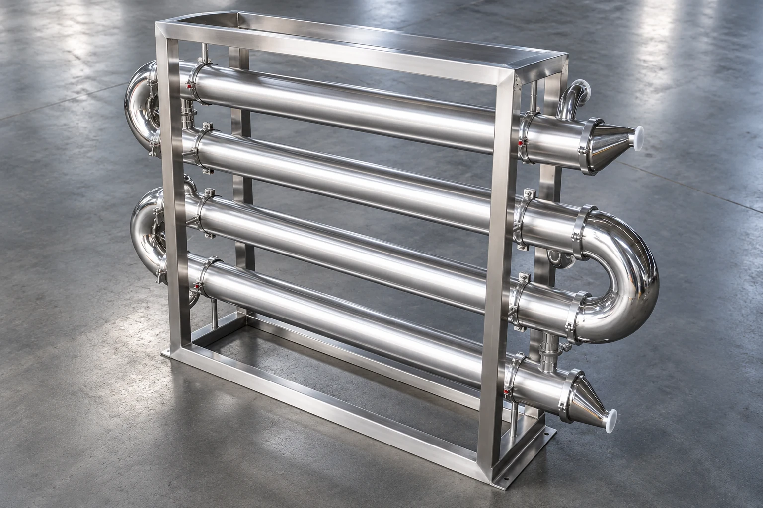
Fouling resistance in a heat exchanger is the additional thermal resistance associated with deposits on heat-transfer surfaces. It reduces the effective overall heat-transfer coefficient and can increase the area required to deliver a specified duty. Buyers should distinguish a design allowance from an operating estimate, use a consistent area basis and units, and examine the hydraulic consequences of the selected design. A larger fouling allowance is not automatically a safer purchase: it can change exchanger geometry and operation without solving the underlying deposition mechanism.
Distinguish resistance, coefficient, and deposit thickness
Fouling resistance is commonly expressed in square metre-kelvin per watt when using SI units. The overall heat-transfer coefficient, U, is expressed in watts per square metre-kelvin. These quantities are related through the thermal-resistance model, but they are not interchangeable. The expression fouling factor is sometimes used inconsistently, so ask each supplier to define the quantity, units, and area reference stated in its proposal.
Deposit thickness alone does not establish resistance without information about deposit conductivity and the appropriate geometry. Two deposits of the same thickness can influence heat transfer differently. Likewise, a percentage loss of duty is not a direct resistance value. Before comparing proposals, make sure the reported numbers describe the same physical quantity and calculation basis. This simple clarification can prevent a misleading commercial comparison.
Use a consistent thermal-resistance model
In a simplified comparison where clean and fouled coefficients share the same reference area and operating assumptions, total added resistance can be written as R_f,total = 1/U_fouled − 1/U_clean. All coefficients and resistances must use compatible units and bases. The equation should not be applied to measurements taken at unrelated flow rates or fluid conditions and then interpreted as a direct measure of deposited material.
For a tubular exchanger, inside and outside surface areas differ. Side-specific terms must be converted to the chosen area basis in the full calculation. Wall conduction and film resistances also matter. Ask the designer to state the reference area and show how the terms were combined. NPTEL’s heat-transfer teaching slides explain the underlying resistance concept; the exchanger’s actual geometry requires the appropriate engineering model.
Work through an illustrative coefficient calculation
Assume, only for a teaching example, a clean coefficient of 1,000 W/(m²·K) and a combined added resistance of 0.0002 m²·K/W on the same area basis. The fouled coefficient is 1 / (1/1,000 + 0.0002), or approximately 833 W/(m²·K). The resistance terms add; the coefficient does not decrease by simply subtracting the resistance value. These hypothetical inputs are not recommended design factors for any named fluid or Yiyi equipment.
If duty and corrected temperature driving force were held unchanged in a simplified area calculation, the required area ratio would be U_clean/U_fouled, approximately 1.20 in this example. A real redesign does not necessarily preserve those assumptions: altered geometry can change film coefficients, velocities, pressure loss, and flow distribution. Use the example to understand sensitivity, not to specify a twenty-percent area margin without further analysis.
Compare design allowance with measured operation
A design allowance represents an engineering assumption for future operating conditions. An operating estimate derived from performance data reflects the exchanger and measurement conditions at the time of evaluation. They answer different questions. A measured decline in apparent U may also contain effects from changed properties, flow distribution, sensor errors, or unaccounted losses. Do not label every change in calculated coefficient as confirmed deposit growth.
Create a clean baseline after an approved commissioning or cleaning procedure. Compare later data using consistent calculation methods and relevant operating conditions. The heat exchanger fouling guide addresses causes and prevention; this article focuses on resistance, sizing, and proposal interpretation. The topics are complementary rather than two interchangeable purchasing pages.
Build a calculation-basis checklist for quotations
The following table helps compare proposals without inventing fluid-specific fouling values. Each numerical allowance should have an identified engineering basis and a clear responsibility for approval.
| Barang | Apa yang harus dinyatakan | Mengapa itu penting |
|---|---|---|
| Resistance quantity | Side-specific or combined allowance | Prevents mixing different definitions |
| Units | SI or another explicitly identified system | Avoids direct comparison of incompatible numbers |
| Area basis | Inside, outside, or another defined reference | Keeps resistance and coefficient terms consistent |
| Operating case | Flows, properties, temperatures, duty | Makes proposal sensitivity interpretable |
| Cleaning assumption | Expected method and operating interval basis | Connects design allowance to maintenance strategy |
| Hydraulic result | Pressure drop and relevant velocities | Shows consequences of geometry and distribution |
| Evidence source | Process history or approved design method | Separates justified inputs from arbitrary margins |
Examine both thermal and hydraulic consequences
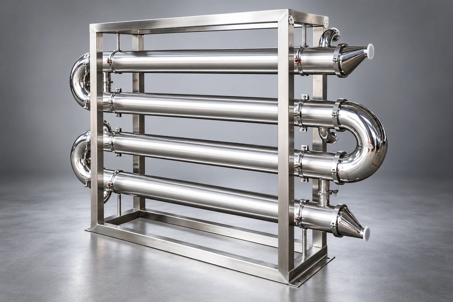
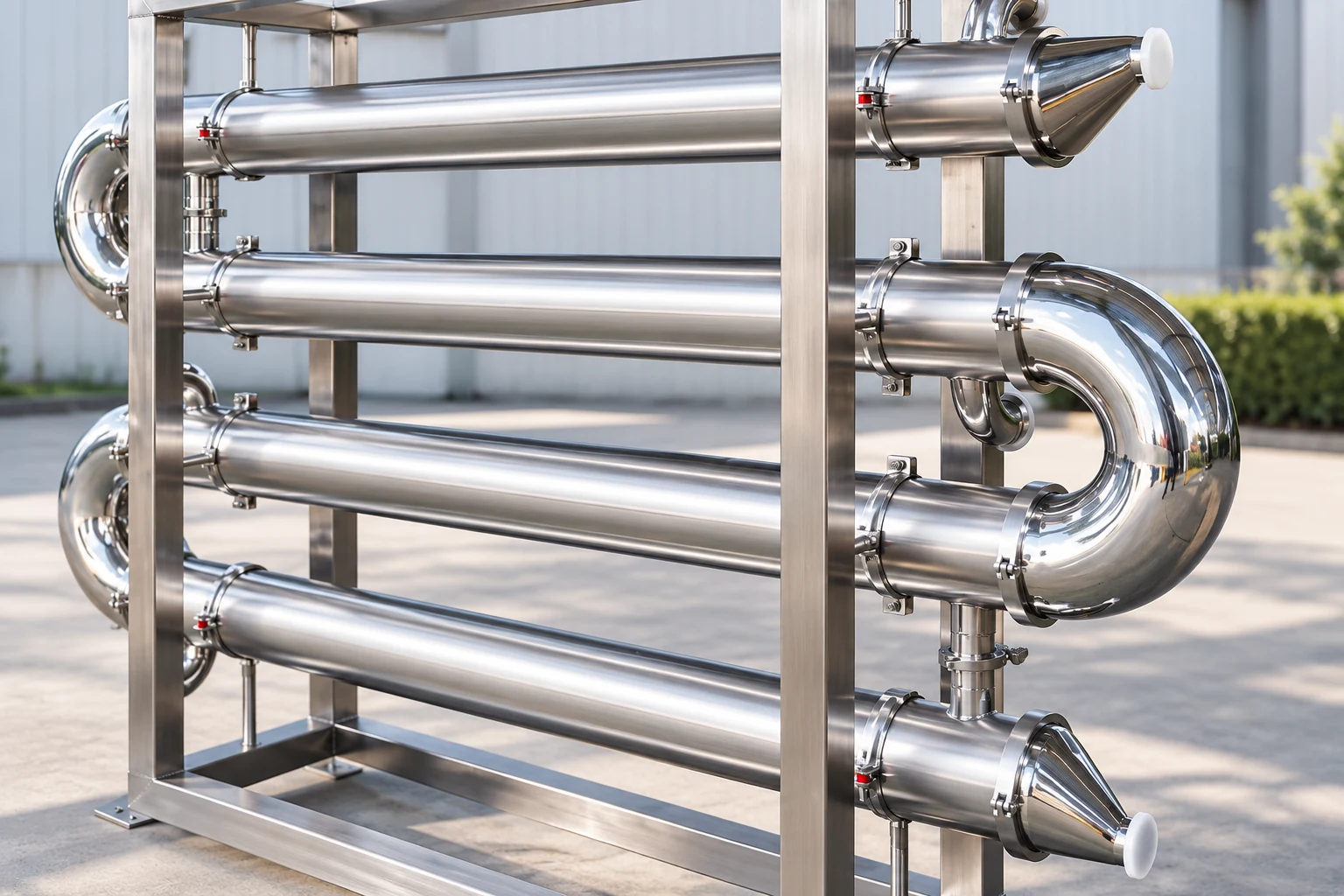
Additional surface area can be obtained through different changes in geometry. More parallel flow paths may reduce velocity; longer paths may increase pressure loss; other changes can alter distribution. The resulting design may therefore have a different deposition tendency and pumping requirement. Ask for the thermal and hydraulic calculations together. A proposal that shows only a larger area does not explain whether the revised configuration remains suitable for the process.
Review the available pump and utility conditions, permitted pressure drop, cleaning access, and material compatibility. When bids use different constructions, compare them against the same operating envelope rather than treating nominal area as the sole ranking criterion. The shell-and-tube maintenance guide helps identify service-access consequences that can be overlooked during a thermal comparison.
Avoid arbitrary fouling-factor tables without context
A published value can be a starting point only when its fluid, temperature, service history, and design basis are relevant. Water quality, suspended material, reaction conditions, biological activity, and operating practice can vary widely between installations. Do not select the most conservative-looking number from an unrelated table and assume it covers every uncertainty. Ask which conditions the source represents and whether the plant can reasonably maintain them.
Where trustworthy operating history is available, use it to inform the review together with appropriate engineering judgment. State limitations such as a different cleaning interval, changed feed, or seasonal utility variation. Where history is absent, document the assumption and arrange a performance-monitoring plan. The objective is an accountable design basis, not a falsely precise resistance value that appears authoritative because it contains several decimal places.
Estimate operating resistance only from suitable data
For a steady single-phase service, determine duty from an appropriate energy balance using documented fluid properties. Calculate the relevant driving force and coefficient with the exchanger’s actual arrangement and reference area. Review stability, losses, and measurement uncertainty before interpreting the result. Phase-changing fluids or strongly varying properties may require an enthalpy-based or more detailed model rather than a simple constant-heat-capacity calculation.
Compare the derived coefficient with a valid clean reference or model under comparable conditions. If the clean coefficient itself changes with flow or properties, use a method that accounts for those changes. A resistance estimate should identify its uncertainty and assumptions. Negative apparent resistance can indicate inconsistent conditions, measurement error, or model limitations; it is not evidence that deposits have created negative thermal resistance.
Interpret pressure drop as supporting evidence
Rising pressure drop can support a fouling investigation, but compare it at relevant flow, fluid, and temperature conditions. A hydraulic change can also come from valve positions, strainers, pumps, gas accumulation, or other parts of the system. Conversely, a thermal deposit may reduce heat transfer before a large hydraulic change is observed. Neither a pressure trend nor a temperature trend should be treated as a complete diagnosis on its own.
Track thermal and hydraulic indicators alongside process events and cleaning records. Inspect the evidence for changes in feed or utility conditions before assigning a cause. Set investigation and maintenance criteria through an approved site strategy rather than an arbitrary universal threshold. The heat exchanger introduction provides broader equipment context, while this resistance analysis supplies one part of an informed operating review.
Connect resistance assumptions to cleanability
A useful allowance assumes an operating and maintenance strategy that the site can actually perform. Confirm access, acceptable cleaning methods, material compatibility, required outage time, and waste-handling responsibilities. A design that depends on frequent cleaning may be unsuitable where production cannot tolerate the interruptions. Equally, extra area does not replace the need to assess deposits that create plugging, corrosion, product contamination, or process instability.
Ask how cleaning effectiveness will be evaluated. A return toward the original coefficient under comparable conditions is useful information, but it may not establish that every surface is clean or that no damage remains. Combine thermal evidence with the appropriate inspection and quality requirements. Follow the manufacturer’s approved methods; this article does not prescribe chemicals, concentrations, mechanical cleaning force, or operating limits for a particular exchanger.
Specify the sensitivity study you need from suppliers
Untuk sebuah fixed-tubesheet exchanger enquiry, provide fluids, composition, solids information, flow ranges, temperatures, target duty, pressure limits, utility conditions, available history, and cleaning constraints. Request clean and fouled calculations on one clearly stated area basis. Ask the supplier to show how changes in the assumed resistance affect area, geometry, pressure drop, and expected operating performance.
The comparison should identify limiting cases and the approved basis for guarantees. Include alternative constructions when service access or contamination control matters. State which fouling assumptions the purchaser must confirm and which are supplied by the designer. Do not accept an unexplained total safety margin as a substitute for a documented sensitivity study. A transparent proposal makes later baseline measurements and performance disputes much easier to interpret.
Educational video and references
LearnChemE’s Heat Exchanger simulation illustrates temperature profiles and the driving force used in exchanger calculations. It is useful context for understanding why lower effective U changes the required area or achieved duty; it does not provide fluid-specific fouling allowances.
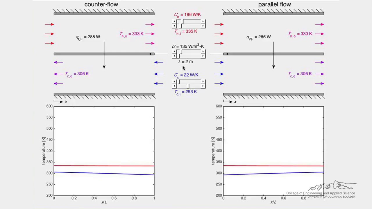
Watch Heat Exchanger (Simulation) by LearnChemE
Further fundamentals: Sumber daya transfer panas LearnChemE dan LearnChemE material and energy balances. Product-specific design and cleaning decisions require the actual supplier’s verified calculations and instructions.
Pertanyaan yang sering diajukan
Is fouling resistance the same as percentage duty loss?
No. Resistance is part of the thermal model. Duty also depends on area, flow conditions, temperatures, and exchanger arrangement. A percentage duty change cannot be converted to resistance without a suitable basis.
Should the highest allowance always be selected?
No. Assess the source, operating assumptions, hydraulic consequences, and maintenance strategy. An arbitrary larger allowance may change the design without resolving the deposition risk.
Can two supplier values be compared directly?
Only when definition, units, side allocation, area basis, and operating assumptions are compatible. Ask suppliers to present the comparison on an agreed common basis.