

Counterflow vs parallel flow heat exchanger comparisons begin with direction: in ideal counterflow, the streams travel in opposite directions; in parallel flow, they enter the same end and travel in the same direction. At equal inlet temperatures, heat-capacity rates, and thermal conductance, ideal counterflow generally transfers at least as much heat as ideal parallel flow. That advantage does not prove every shell-and-tube product operates as pure counterflow. Pass arrangements, shell-side mixing, bypasses, and practical constraints must match the thermal model. Compare the complete proposed arrangement, duty, pressure losses, and operating conditions before choosing equipment.
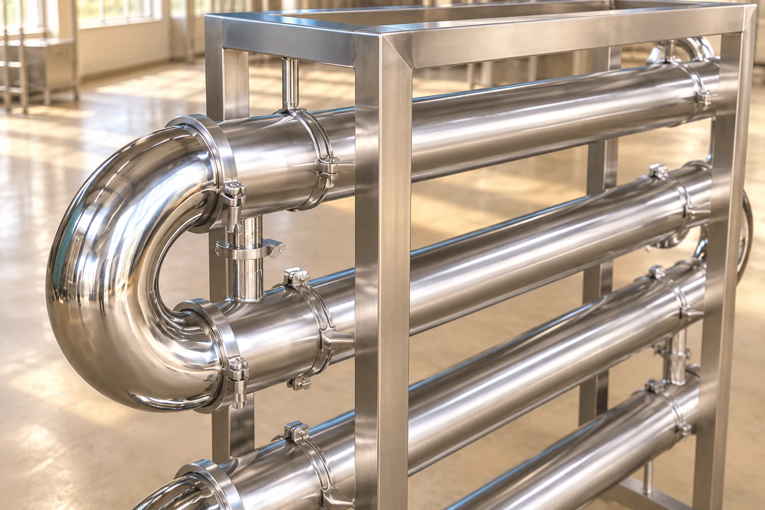
This guide explains the temperature profiles and provides a checked example for purchasing discussions. Our tubular exchanger guide covers equipment selection. The sanitary tubular exchanger product page supplies product context; its visible return bends do not establish the internal stream arrangement or a guaranteed thermal performance.
Draw both streams before comparing temperatures
In parallel flow, both inlet streams meet at one end. Their temperature difference is initially large and decreases along the flow path. In ideal counterflow, each stream’s inlet lies near the other stream’s outlet. The temperature-driving difference is distributed differently along the length. Label hot inlet, hot outlet, cold inlet, and cold outlet on a sketch rather than relying on a diagram whose arrow meanings are unclear.
Keep physical location separate from the inlet/outlet label. Counterflow outlets occur at opposite ends, so comparing the two outlet values alone does not give a local driving difference. In some ideal counterflow cases, the cold outlet is hotter than the hot outlet while every local heat transfer still proceeds from hotter to colder fluid. It remains below the hot inlet in the ordinary sensible-heat model.
Establish a fair comparison basis
To compare performance, hold the hot and cold inlet temperatures, heat-capacity rates, and conductance UA constant, then predict duty and outlet temperatures for each arrangement. To compare required conductance instead, hold a physically achievable duty and terminal conditions constant. Those are different comparisons. A larger exchanger in parallel flow should not be compared with a smaller counterflow unit and used to infer the effect of direction alone.
Define C = ṁcp for each stream, with mass flow in kg/s and specific heat in kJ/(kg·K), giving C in kW/K. Identify Cmin, Cmax, and Cr = Cmin/Cmax. For the simple steady single-phase model, maximum possible duty is Qmax = Cmin(Th,in − Tc,in). State negligible external loss and consistent property assumptions. Significant property variation, phase change, or unusual mixing needs an appropriate extended model.
Compare ideal effectiveness relationships
Let NTU = UA/Cmin and effectiveness ε = Q/Qmax. For ideal parallel flow, ε = [1 − exp(−NTU(1 + Cr))]/(1 + Cr). For ideal counterflow with Cr ≠ 1, ε = [1 − exp(−NTU(1 − Cr))]/[1 − Cr exp(−NTU(1 − Cr))]. At Cr = 1, the counterflow limit is ε = NTU/(1 + NTU). These relationships are for their stated ideal models, not every multipass exchanger.
El NPTEL effectiveness–NTU lecture gives the academic method context. Use a relationship appropriate to the actual flow arrangement and mixing. The equations do not determine UA from a product photograph. A justified overall coefficient, area basis, and fouling condition are still needed before they can rate a particular piece of equipment.
Work the same inputs in both arrangements
Take an illustrative hot inlet of 80 °C and cold inlet of 20 °C. Let the hot heat-capacity rate be 2 kW/K, the cold rate 1 kW/K, and UA = 1.386294 kW/K. Therefore Cmin = 1 kW/K, Cr = 0.5, NTU = 1.386294, and Qmax = 60 kW. These are assumed teaching inputs, not measured YIYI product data. They deliberately match a simple constant-property model so direction can be isolated.
For counterflow, exp[−NTU(1 − Cr)] = 0.5, giving ε = 0.5/0.75 = 0.666667. Duty is 40 kW. The hot outlet is 80 − 40/2 = 60 °C and the cold outlet is 20 + 40/1 = 60 °C. Equal outlet temperatures are feasible here because the outlets are at opposite ends. The terminal differences are 20 K and 40 K, both positive.
For parallel flow, exp[−NTU(1 + Cr)] = 0.125. Effectiveness is 0.875/1.5 = 0.583333, duty is 35 kW, the hot outlet is 62.5 °C, and the cold outlet is 55 °C. The local outlet-end difference is 7.5 K. The result demonstrates the arrangement effect under identical assumed inputs. It does not justify a universal percentage advantage for counterflow at other conditions.
Read the comparison table with its assumptions
The table combines the checked example with qualitative review questions. Numerical rows apply only to the teaching inputs above. The independent LearnChemE parallel-and-counterflow simulation provides an interactive way to explore changes without treating this example as a product guarantee.
| Elemento de comparación | Ideal counterflow | Ideal parallel flow |
|---|---|---|
| Inlet locations | Opposite ends | Same end |
| Example effectiveness | 0.666667 | 0.583333 |
| Example duty | 40 kW | 35 kW |
| Example hot outlet | 60 °C | 62.5 °C |
| Example cold outlet | 60 °C | 55 °C |
| Outlet interpretation | Compare local terminal pairings | Both outlets are at the same end |
| Product approval question | Does the model match actual passes and mixing? | Does the model match actual passes and mixing? |
Connect the result to LMTD
For counterflow, pair Th,in with Tc,out and Th,out with Tc,in. For parallel flow, pair the two inlets and the two outlets. For positive unequal differences, LMTD = (ΔT1 − ΔT2)/ln(ΔT1/ΔT2). In the counterflow example it is 20/ln(2), about 28.85 K; in the parallel example it is 52.5/ln(8), about 25.25 K. Multiplying by the same UA reproduces 40 kW and 35 kW, respectively.
This is an arithmetic cross-check rather than an independent measurement of coefficient or area. For actual multipass shell-and-tube duty, use an appropriate correction or detailed rating. The NPTEL multipass-exchanger lecture explains the correction-factor context. Do not silently set the factor to unity because inlet and outlet nozzles appear at opposite ends.
Recognize where ideal descriptions stop helping
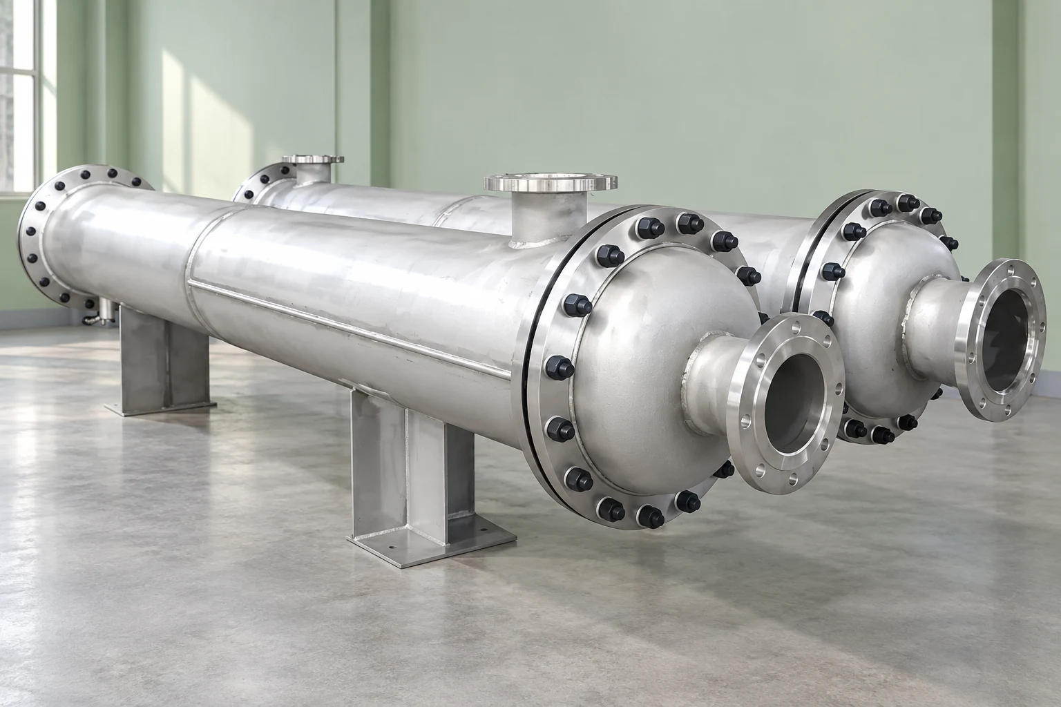
Shell-and-tube equipment can combine countercurrent and cocurrent regions as the tubes reverse direction through successive passes. Shell-side crossflow and mixing further change the temperature field. Obtain a flow sketch and arrangement designation, and ask which mathematical model was used. A supplier’s statement “counterflow type” should be supported by the thermal rating rather than replacing it.
For condensing or boiling service, the relationship between phase region, pressure, and temperature requires a suitable analysis. When one stream is approximately isothermal, the ideal direction advantage may differ from the sensible-heat example. Also review local pinch conditions, approach limits, and uncertainty in measured temperatures. Use the predicted temperature profile to identify where the practical constraint occurs instead of relying on outlet values alone.
Keep direction separate from pressure loss
A reversal of external piping does not automatically improve an existing exchanger or preserve its venting, drainage, controls, and mechanical suitability. The approved nozzle arrangement and operating procedure govern what changes are permissible. Before proposing a direction change, ask the responsible engineer and supplier to review the actual equipment, duty, fluid allocation, and any consequences for startup or shutdown.
More passes may change velocity, losses, and thermal performance together. Compare both-side pressure allowances with the same geometry used for the thermal model. Maintenance access and fouling assumptions also matter: an attractive clean thermal result may not persist under service conditions. Our fouling prevention guide y Guía de mantenimiento del paquete cover complementary operating considerations.
Use neutral learning tools with the right scope
The LearnChemE video below introduces exchanger simulation variables and temperature behaviour. Together with the linked interactive direction comparison, it helps a procurement team interpret thermal results. It does not certify the flow path, construction, or performance of the photographed equipment. Write down the assumptions used in an exercise so the illustrative result is not copied into an RFQ as an equipment requirement without review.
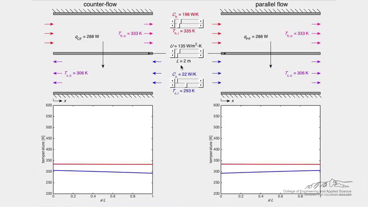
Ver el intercambiador de calor (simulación) de LearnChemE
Ask for a proposal that can be checked
Provide stream identities, compositions, inlet temperatures, minimum/normal/maximum flows, desired duty or outlet target, available utility conditions, and separate pressure-loss allowances. Request the arrangement drawing, property basis, clean and fouled coefficients, conductance, predicted outlets, and model or correction used. If the preferred direction conflicts with drainage or maintenance, request a documented alternative rather than an unexplained promise of equivalent performance.
For acceptance, identify each temperature sensor’s location, calibrations, stable-flow conditions, and measurement uncertainty. Compare hot-side and cold-side energy balances and investigate significant disagreement before inferring UA. A four-temperature record without flow and properties cannot establish a complete thermal rating. Agree how the result will be interpreted if the actual inlet conditions differ from the design case.
Choose the arrangement for the complete duty
Ideal counterflow is a useful thermal benchmark, especially when a close temperature approach is important. Select the purchased construction on a broader basis: required duty, actual pass configuration, losses, materials, maintainability, controls, and service limits. Ask YIYI to review the operating data and provide an arrangement-specific proposal. A good comparison explains why the recommended configuration meets your conditions rather than attaching a general efficiency claim to a product name.
Preguntas frecuentes
Can a counterflow cold outlet exceed the hot outlet?
Yes, in suitable ideal sensible-heat cases, because the outlets are at opposite ends. Check local temperature differences and the energy balance. This does not mean heat flows from colder to hotter material.
Is every multipass shell-and-tube exchanger pure counterflow?
No. Pass changes, mixing, and shell-side flow create a more complex arrangement. Use the appropriate rating method and drawing rather than applying an ideal equation without justification.
Does counterflow always need less area?
It can offer a larger effective driving difference for suitable comparable duties. The actual area also depends on coefficient, correction, geometry, and operating limits. Some specified parallel-flow temperature targets may be infeasible under the assumed model.
Can I reverse the pipes to improve an installed unit?
Do not assume so. Review approved connections, venting, drainage, controls, fluid allocation, and equipment limits with the responsible engineer and supplier before changing the operating arrangement.


