

A heat exchanger tube plugging assessment asks whether the remaining equipment can safely meet its revised mechanical, thermal and hydraulic duty after selected tubes are isolated. The answer depends on the damage mechanism, tube locations, pass arrangement, plug design and actual operating cases. A universal percentage of plugged tubes cannot establish acceptance. This guide helps owners prepare the tube map, operating evidence and engineering questions needed for a defensible continued-service decision. It is not a tube-plug installation procedure, a pressure-equipment approval or permission to operate with unresolved leakage.
Define the decision before selecting a repair
Begin with the reason for the assessment. A leaking tube discovered during an outage, a recurring cross-contamination concern and a planned life-extension review require different evidence. Record the current operating restriction and the person responsible for approving the next step.
Distinguish an immediate isolation decision from long-term repair acceptance. Stopping a leak does not establish the condition of neighboring tubes, the remaining thermal capacity or the durability of the selected repair. The team should state which questions have been answered and which still require inspection or calculation.
For the broader repair-versus-renewal decision, use the retubing and replacement guide. The present article focuses on the records and rerating needed when continued operation with isolated tubes is being considered.
Preserve a reliable tube map
A tube map identifies the exchanger, viewed end, pass partition, row and tube position. Use a controlled orientation and preserve the drawing revision. A photograph with colored marks is useful supporting evidence, but it can become ambiguous if the view is reversed or a pass boundary is omitted.
Record every existing plug and every newly proposed plug. Include the installation date when known, plug identification, tube location, reason for isolation and supporting inspection report. Distinguish confirmed information from reconstructed history. An unknown old plug should not be treated as a fully documented repair.
For multi-pass equipment, account for the affected pass rather than relying only on a whole-bundle total. Two equal totals can have different consequences when the isolated tubes are distributed differently. Ask the designer to reconcile the map with the actual flow arrangement before calculating a revised operating envelope.

Establish why the tubes degraded
The assessment should connect each affected tube to inspection evidence and a credible damage mechanism. Corrosion, erosion, cracking and mechanically induced wear can have different implications for inspection coverage and future deterioration. A visible leak identifies a loss of containment; it does not by itself explain why the loss occurred.
The responsible inspection specialist should select suitable examination methods, coverage and interpretation criteria. Tube material, geometry, access, deposits and the suspected mechanism affect what a method can detect. Record limitations explicitly so an unexamined region is not mistaken for a sound region.
Evaluate relevant adjacent tubes and common operating conditions. If a mechanism can affect many tubes, isolating only the first leaking tube may leave the wider problem unresolved. Keep the root-cause investigation and the plug-selection decision connected, while recognizing that each needs its own evidence.
Separate pressure integrity from thermal performance
Mechanical acceptance concerns the pressure boundary, tube-to-tubesheet arrangement, repair method and the behavior of the isolated tube under relevant pressure and temperature cases. Thermal acceptance concerns whether the remaining active surface and flow arrangement can deliver the required duty. Passing one review does not automatically pass the other.
El Guía de sistemas de presión de HSE describes the wider responsibilities associated with pressure equipment in its jurisdiction. Apply the code, jurisdiction, inspection scheme and responsible engineering authority appropriate to the actual installation. Do not transfer a legal requirement from one location without checking applicability.
Ask the repair specialist how the proposed plug system is qualified for the specific tube material, dimensions, condition, pressure, temperature and service. This article deliberately provides no insertion depth, torque, welding instruction or test pressure. Those values belong to an approved equipment-specific procedure.
Prepare a review package with clear ownership
The following table organizes the continued-service review. It does not prescribe a safe plugging fraction or replace the responsible engineer’s acceptance criteria.
| Elemento de revisión | Evidence required | Decision to document |
|---|---|---|
| Equipment configuration | Current drawing, pass layout, tube dimensions and complete plug map | Does the calculation represent the as-found exchanger? |
| Damage mechanism | Examination reports, locations, operating history and investigation findings | Is the remaining inspection coverage adequate? |
| Repair suitability | Qualified procedure and plug-system documentation for the actual service | Is the repair method acceptable for this equipment? |
| Carga térmica | Required load, inlet conditions, fluid properties and revised rating | Can the reduced active bundle meet each required case? |
| Hydraulic behavior | Pass-specific active area, revised pressure loss and system operating point | Are flow and pressure constraints still satisfied? |
| Monitoring and life | Inspection plan, triggers, expected service period and responsibility | What changes require restriction, inspection or withdrawal? |
Each decision should identify its reviewer, assumptions and supporting document. A summary stating only “acceptable” is difficult to reassess when the service changes.
Recalculate flow area using the affected pass
A simple screening calculation can show why location matters. For equal internal tube diameters and a known pass arrangement, the active flow area of one pass is the number of active tubes in that pass multiplied by the internal area of one tube. Average tube velocity is the volumetric flow through that pass divided by its active flow area.
As an illustrative example, suppose a pass originally contains 100 equal active tubes and 10 are isolated. Its active area becomes 90 percent of the original. If the same volumetric flow is maintained, the simple average velocity ratio is 100 divided by 90, approximately 1.11. This is an arithmetic illustration, not a permitted plugging percentage or a safe velocity recommendation.
The calculation assumes equal tube dimensions, the same pass flow, no bypass and an understood configuration. It does not predict pressure loss, local distribution, fouling, vibration or mechanical acceptance. A different pass layout or a changed pump operating point requires a different assessment. Use the guía de velocidad del tubo to organize the inputs rather than treating the example as a design result.
Rerate the complete thermal and hydraulic duty
Removing active tubes changes available surface and flow conditions, but the resulting duty does not necessarily decline by the same percentage as the tube count. Heat-transfer coefficients, flow distribution, fouling allowances and temperature differences can change together. Ask for a revised rating with the actual plug map and required operating cases.
The review should consider the connected system. If resistance increases, a pump may deliver a different flow rather than maintain the old flow automatically. A control valve can also move to a new position. Therefore, verify the system operating point and available control margin rather than inserting the former flow into every calculation without review.
El Material didáctico de intercambiadores de calor NPTEL provides background on heat-exchanger analysis. Site acceptance still requires current equipment and process inputs. Record fluid-property assumptions and distinguish measured temperatures and flow rates from estimated values.
Include startup, shutdown and changed service
The most demanding case may not be normal steady operation. Review the applicable pressure and temperature differences during startup, shutdown, cleaning, standby and credible abnormal conditions. Ask the responsible repair engineer how the isolated tube and plug arrangement behave under those cases.
A later change in service can invalidate an earlier assessment. Higher flow, a different fluid, altered pressure or a new cleaning method should trigger review through the site’s change process. Preserve the original approval conditions in an accessible equipment record so they can be compared with the proposed change.
Consider whether the required inspection and maintenance access remains available. A temporary continued-service decision should define its duration or next inspection condition. Without that boundary, a short-term repair can remain in service long after the assumptions supporting it were intended to apply.

Set monitoring and withdrawal criteria before restart
Specify which operating measurements will be trended and under what comparable conditions. Useful records may include inlet and outlet temperatures, flow, pressure loss and evidence relevant to cross-contamination. Measurement quality matters: inconsistent sensor locations or changed operating conditions can make apparent trends misleading.
El performance-monitoring guide explains how to organize comparable records. A monitoring plan should state the action required when a limit, change or unexplained discrepancy appears. It should identify who reviews the data and who can restrict operation.
Do not use apparently stable thermal performance as proof that the pressure boundary is sound. Conversely, an accepted pressure test does not guarantee that the exchanger meets the required process duty. Keep containment verification, thermal acceptance and longer-term inspection as separate recorded conclusions.
Ask the supplier for a reviewable disposition
Para un Cambio de tubos fijo de Kanger, provide equipment identification, approved drawings, the current tube map, examination findings and the required revised duty. The closed exterior shown in the product illustration cannot establish tube condition or an allowable number of isolated tubes.
Request an assessment that states the accepted configuration, operating restrictions, inspection requirements and circumstances that would trigger retubing or replacement review. If information is missing, ask which additional measurement or document is needed. A clear unresolved item is more useful than an unsupported assurance that a familiar percentage is usually acceptable.
Before restart, reconcile the approved assessment with the completed repair and final map. Preserve the installation record, inspection disposition, verification results and monitoring instructions together. The resulting file should let a later engineer understand both what was changed and why continued service was accepted.
Video educativo
The following university lecture introduces heat-exchanger testing. It provides context for performance evidence and does not authorize a tube repair or establish mechanical acceptance criteria.
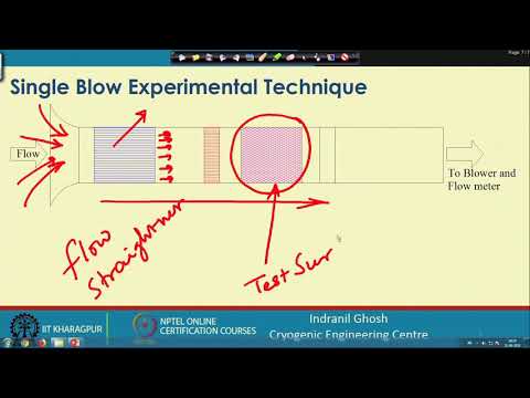
Watch Lecture 65 : Heat Exchanger Testing by NPTEL IIT Kharagpur
Preguntas frecuentes
Is there one safe percentage of heat exchanger tubes that can be plugged?
No universal percentage establishes acceptance. The tube locations, pass arrangement, damage mechanism, repair design and revised operating duty need an equipment-specific assessment.
Does plugging ten percent of tubes reduce duty by exactly ten percent?
No. Active surface, flow distribution, heat-transfer coefficients and the system operating point can change together. The revised duty requires a thermal and hydraulic rating.
What records should be retained after tube plugging?
Retain the final oriented tube map, inspection findings, approved repair procedure, installation record, verification results, revised rating and operating restrictions, together with the monitoring and next-inspection plan.


