

Shell and tube heat exchanger pressure drop is the pressure loss a fluid experiences between defined inlet and outlet measurement points. It includes losses through the flow passages and, depending on the agreed boundary, nozzles, headers, and changes of direction. Specify separate allowable losses for the shell side and tube side at stated flow rates, temperatures, and fluid properties. There is no universal acceptable value: the available pump head, process pressure requirements, fouling allowance, and operating range determine the limit. A unit that meets heat duty can still be unsuitable if its hydraulic resistance prevents the required flow.
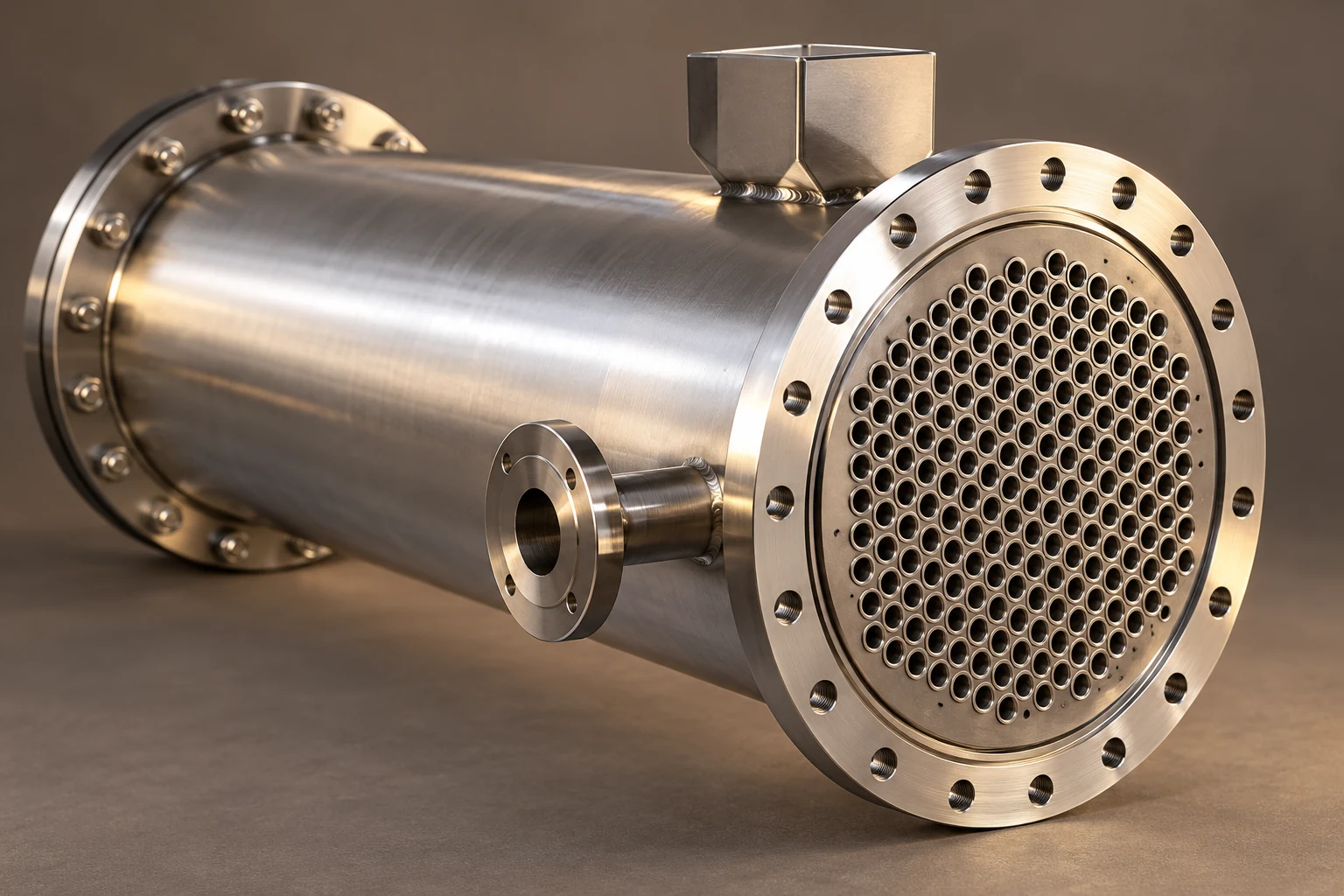
This guide helps buyers define a meaningful hydraulic guarantee and troubleshoot changes after installation. Our tubular exchanger buyer’s guide provides the broader equipment context. YIYI’s fixed-tube-sheet exchanger product page illustrates a product configuration; the photographs do not establish an allowable pressure loss or operating rating.
Establish the measurement boundary first
Write the boundary directly into the inquiry: for example, exchanger inlet nozzle to exchanger outlet nozzle, excluding the upstream strainer and downstream control valve. A bundle-only calculation cannot be compared with measurements that include several metres of piping. Record whether pressure taps lie at different elevations and whether the reported result is a raw instrument differential or a corrected hydraulic loss. Use the same definition for the quoted limit and acceptance test.
Identify each stream independently. A single statement such as “low pressure drop required” does not tell the designer which side is constrained or how much head is available. The process engineer should allocate the total circuit resistance among exchanger, piping, valves, filters, and other equipment. Leave the supplier an explicit exchanger allowance rather than expecting the exchanger to absorb an unspecified remainder.
Understand the tube-side contributors
Inside the tubes, wall friction depends on geometry, flow, fluid properties, and the applicable flow regime. Channel entries, exits, and pass changes introduce additional losses. The NPTEL lecture on exchanger pressure drop distinguishes tube friction from return losses and treats the shell side separately. This distinction is useful when reviewing whether a submitted calculation covers the complete equipment boundary.
More passes do not simply add a fixed penalty. They also change the number of tubes carrying the stream in parallel and therefore the velocity for a given total flow. Ask for the tube count per pass, inside diameter, effective flow length, and entrance assumptions. Two designs with the same total tube count may have substantially different hydraulic behaviour because their pass arrangements differ.
Review shell-side geometry and distribution
Shell-side resistance depends on the actual flow path around the tube bundle, including baffle windows, crossflow regions, and entrance or exit zones where applicable. Bypass and leakage streams can influence both resistance and heat transfer. A simple unbaffled model should not be accepted as a complete rating of a baffled arrangement without an explanation. Obtain the arrangement drawing and the stated correlation or rating method.
Changing baffle spacing to reduce resistance also affects tube support and thermal performance. This is a design review, not an adjustment to make casually after purchase. Ask the supplier to assess the revised geometry together with vibration, mechanical support, and duty. The NPTEL worked shell-and-tube design procedure includes separate shell crossflow and return-loss calculations, illustrating why a shell-side total needs a defined basis.
Use a limited example to check units
For a straight, round tube carrying a steady single-phase liquid, an illustrative friction term is ΔP = fD (L/D) ρv²/2, where fD is the Darcy friction factor, L and D are in metres, density ρ is in kg/m³, and velocity v is in m/s. The result is in pascals. Local losses can be represented separately as ΣK ρv²/2 when suitable coefficients and a consistent reference velocity are available. This expression is not a full shell-and-tube rating.
Suppose, purely for arithmetic illustration, fD = 0.025, L = 6 m, D = 0.020 m, ρ = 1,000 kg/m³, and v = 1.5 m/s. The straight-tube friction term is 0.025 × 300 × 1,125 = 8,437.5 Pa, or about 8.44 kPa. If the assumed local-loss sum is K = 3, its contribution is 3.38 kPa, giving about 11.81 kPa before other excluded losses. The assumed factor and coefficients are inputs, not recommended design constants. Darcy and Fanning factors use different conventions; confusing them causes a factor-of-four error in the friction term.
Compare proposed changes with their consequences
The following qualitative table is an inquiry review aid. It does not assign universal velocities or loss limits. Every proposed change requires a recalculated thermal and hydraulic case using the agreed fluids and arrangement.
| Proposed change | Hydraulic question | Other decision to check |
|---|---|---|
| Increase tube inside diameter | How does velocity change at the specified flow? | Heat-transfer coefficient and cleaning access |
| Increase tubes carrying flow in parallel | Does lower velocity meet the pressure allowance? | Fouling tendency and available surface |
| Reduce tube passes | What return losses and velocity change are predicted? | Thermal arrangement and outlet target |
| Increase baffle spacing | Which shell-side loss components decrease? | Tube support, vibration, and duty |
| Increase nozzle size | Is nozzle resistance a material share of the total? | Piping connection and mechanical requirements |
| Reduce the operating flow | Is the new circuit point feasible? | Required heat duty and process throughput |
Separate clean design from service behaviour
The clean hydraulic baseline should use documented flow and properties. Deposits, plugged passages, or changes in fluid composition can change resistance during service. A fouled thermal coefficient is not itself a hydraulic fouling calculation. Ask how the supplier represents the expected deposits or blocked flow area, and whether the guarantee applies only to clean equipment or to a defined end-of-run condition.
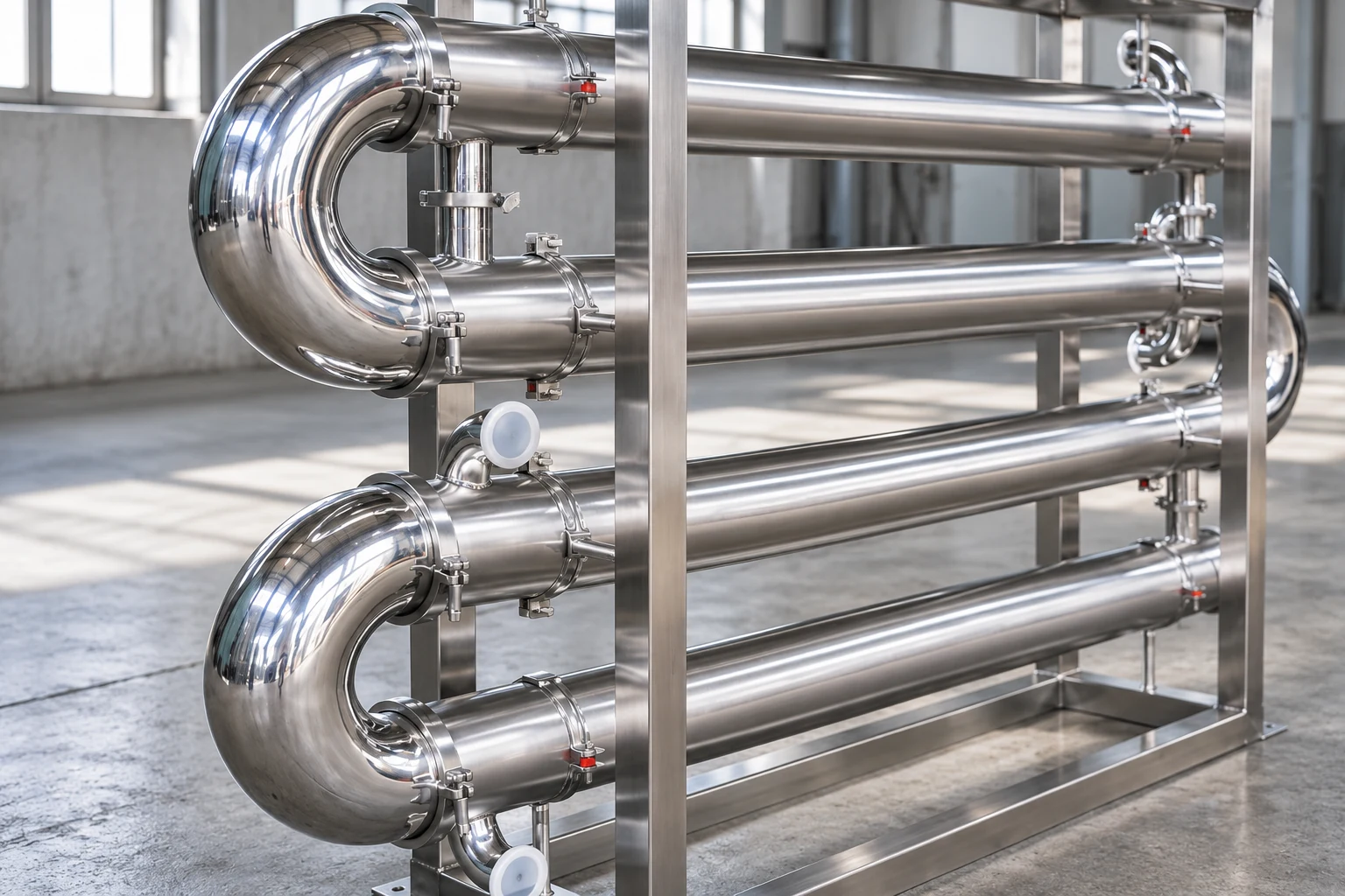
For monitoring, keep differential pressure alongside flow, temperatures, and product condition. A larger measured differential at a higher flow does not alone prove fouling. A lower differential can also be misleading if the pump is delivering less flow or a bypass is open. Our fouling causes and prevention guide addresses deposits as a separate topic rather than treating every pressure change as the same fault.
Diagnose a sudden or gradual change methodically
First confirm instrument function and the comparison conditions. Check the pressure-tap lines, transmitter range, zero, and recorded flow. Then review valve positions, strainers, bypasses, and recent maintenance. Compare a sudden step after startup with a gradual trend across an operating campaign. The timing helps identify which evidence to collect; it does not replace inspection or establish a cause by itself.
If cleaning is considered, define isolation, depressurization, drainage, temperature control, and chemical compatibility before opening equipment. Check the approved maintenance procedure and use competent personnel. Inspect the accessible passages for deposits or damage, retain observations, and compare the post-cleaning result at equivalent conditions. The bundle maintenance planning guide helps identify access requirements before a unit is installed.
Connect pressure loss to pumping cost
For a liquid circuit, hydraulic power associated with an allocated loss is P = ΔP × volumetric flow. With ΔP in Pa and flow in m³/s, the result is watts. For example, 20 kPa at 0.005 m³/s represents 100 W of hydraulic power. Electrical input requires the relevant pump, motor, and drive efficiencies and the complete circuit operating point. This small example is not a prediction of site energy savings.
El US Department of Energy pumping-system resource page provides system-level efficiency context. Evaluate the exchanger with the pump curve and control strategy. An exchanger change that lowers one component’s resistance does not guarantee a proportionate reduction in electricity, especially if the operating flow or valve throttling changes. Record the annual duty pattern before attaching a financial benefit to a redesign.
Keep the thermal tradeoff visible
The neutral LearnChemE simulation below helps explain how exchanger operating conditions affect heat-transfer performance. It is included for thermal context; it does not calculate the pressure loss of this product. Use a documented hydraulic rating alongside thermal results, and ask how the same proposed geometry satisfies both sets of requirements. A visually plausible exchanger or a thermal simulation cannot verify an allowable differential pressure.
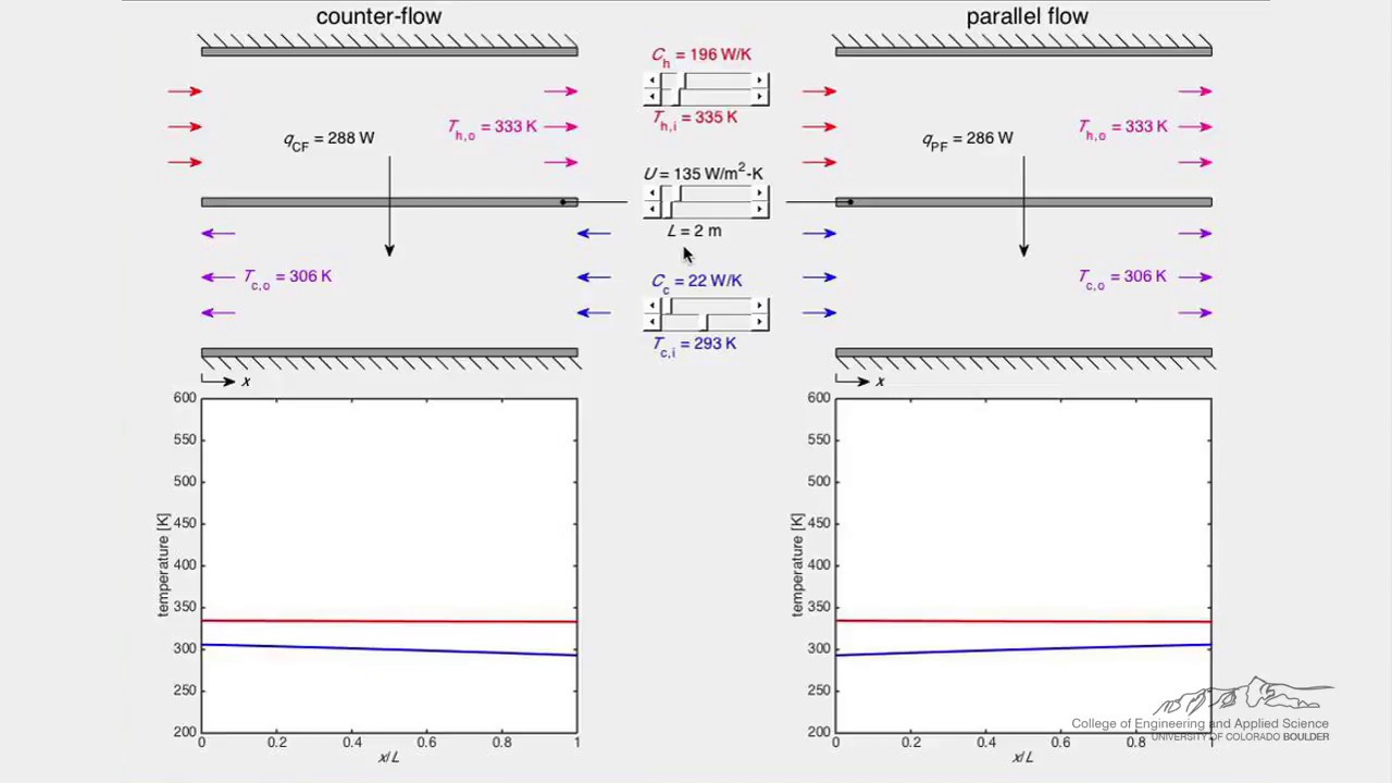
Ver el intercambiador de calor (simulación) de LearnChemE
Write an acceptance test that can be repeated
Agree the test flow, fluid properties, temperature range, measurement boundary, instrument accuracy, and steady-state period before commissioning. Document any elevation correction and the method for averaging fluctuating measurements. Decide how a different test fluid or off-design temperature will be handled. A water-shop test cannot be assumed to reproduce a viscous process stream without a justified interpretation.
Request a separate result for each side and retain the calculation revision linked to the approved drawing. If a measurement exceeds the allowance, first determine whether the test conditions and boundary match the guarantee. Avoid adjusting the acceptance definition after the result is known. Record the agreed response: verify instrumentation, investigate a restriction, review the rating, or carry out an approved modification.
Prepare the supplier inquiry
Send fluid identity and composition, minimum/normal/maximum flows, operating temperatures, density and viscosity basis, heat duty, and separate allowable pressure losses. Add design pressure and temperature, materials, solids or fouling concerns, maintenance method, nozzle requirements, and the intended guarantee boundary. Ask for sensitivity cases where composition or flow is uncertain. The next useful step is a thermal-and-hydraulic proposal tied to those inputs, with every exclusion stated.
Preguntas frecuentes
Is a smaller pressure drop always better?
It helps preserve available head, but the complete design must also meet duty, distribution, cleaning, and mechanical requirements. Compare the operating consequences of each proposed geometry rather than minimizing one reported number alone.
Does high differential pressure prove fouling?
No. Compare flow and properties, check instruments, and investigate valve, strainer, and passage conditions. A trend at equivalent conditions is stronger evidence than an isolated reading, but diagnosis still needs supporting checks.
Can tube-side pressure drop predict shell-side pressure drop?
No. They involve different fluids, geometry, and flow paths. Calculate and specify them separately, including the appropriate losses within each agreed boundary.
Is the worked example a YIYI equipment rating?
No. It demonstrates units and arithmetic for assumed straight-tube inputs. A product rating requires the approved geometry, fluid data, full loss components, and operating cases.


