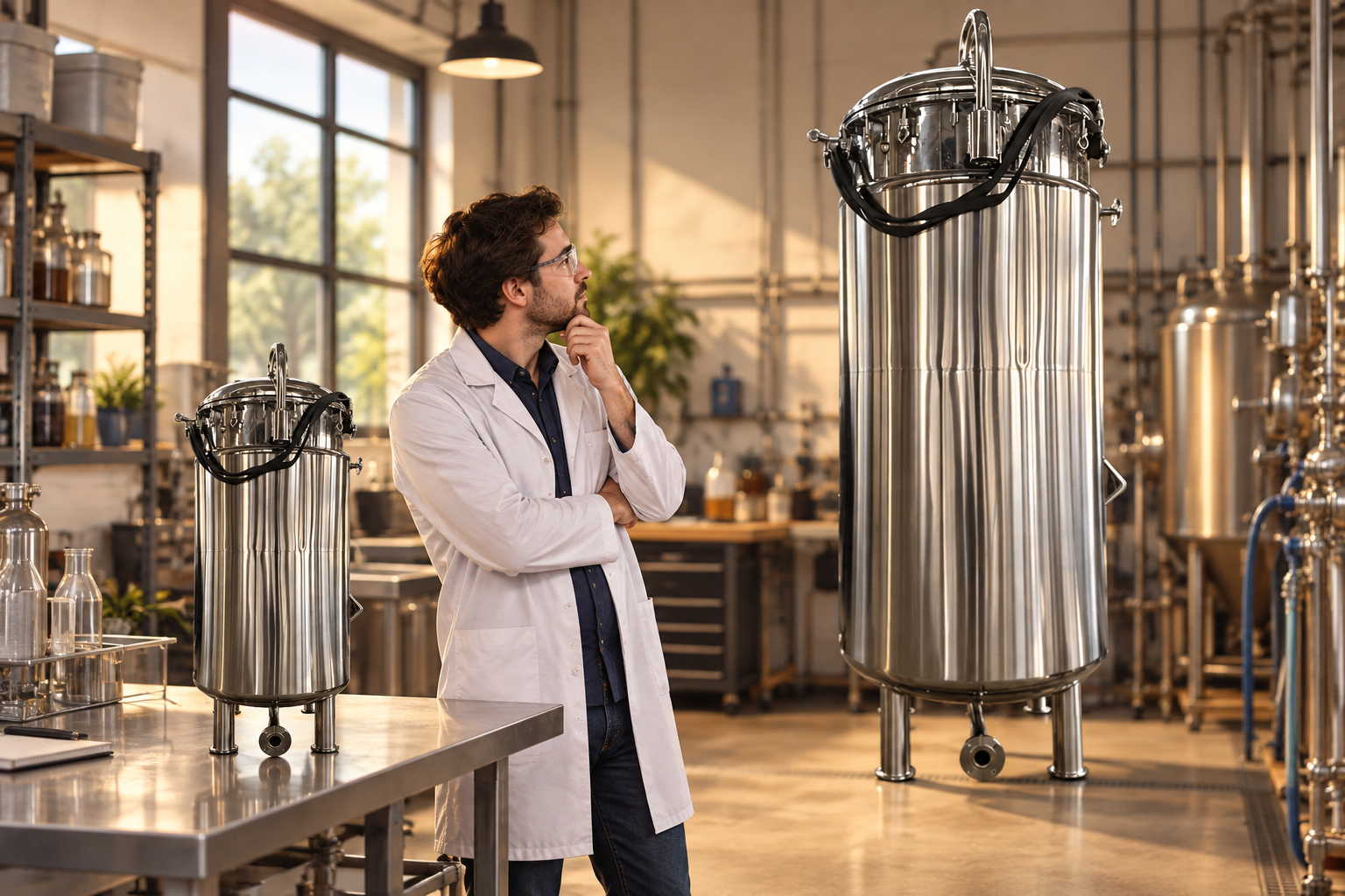
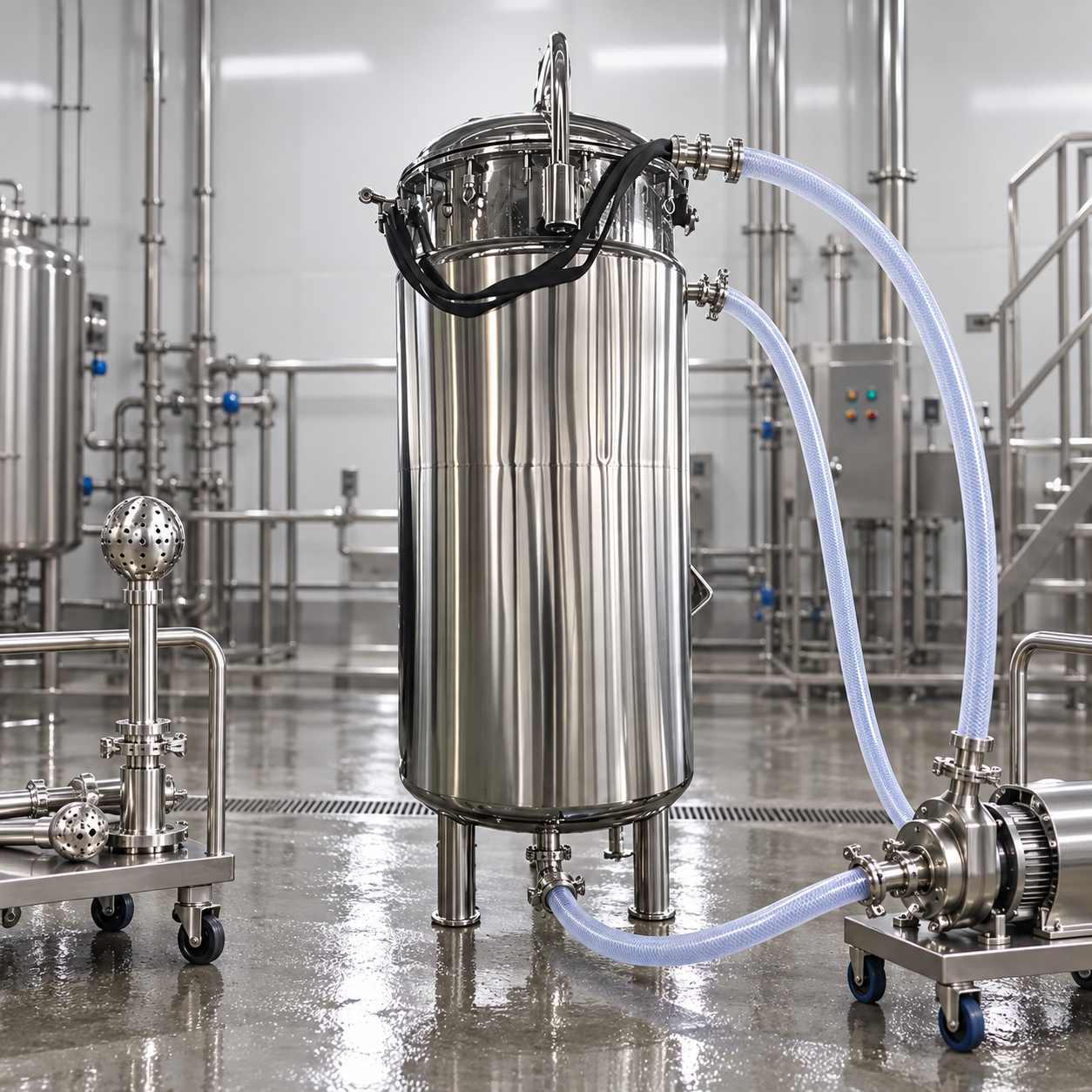
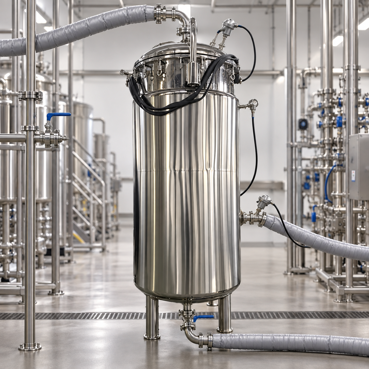
A fermenter cooling load calculation estimates the heat that must be removed at the most demanding point of a batch, not merely the heat needed to cool an empty vessel. Account for metabolic heat, agitator energy, warm feeds, gas effects and any planned temperature ramp; subtract only heat losses that can be justified. Then check that the jacket or coil and the site utility can remove that load at the actual broth and coolant temperatures. The calculation is process-specific: cell activity, fill volume, viscosity and available cooling-water temperature can change through the batch. A useful equipment request therefore includes a heat-balance worksheet, peak operating case and test method rather than a generic chiller rating.
Set the control volume and time window
Define whether the balance covers the broth alone, the vessel wall, the coolant loop, or an external heat exchanger. For initial equipment selection, a liquid-side balance is often the clearest starting point: heat generated and introduced into the broth must equal heat removed plus any change in stored energy. Use a short enough time interval to capture the metabolic peak, feed pulse or rapid temperature transition. Averaging over an entire day can hide a short but important peak.
Write all terms in compatible units, typically kilowatts. One useful form is Qremove = Qmetabolic + Qagitador + Qfeed + Qgas − Qambient loss − Qstored. The signs depend on the chosen control volume. If the broth temperature is being held constant, the storage term is approximately zero for that interval. If it is being cooled deliberately, the required sensible cooling must also be added. Do not count the same agitator energy twice in both a motor term and an empirical metabolic-heat estimate.
Estimate metabolic heat from process evidence
Metabolic heat is usually the hardest input. Prefer calorimetry, a validated oxygen-uptake correlation, or historical heat-removal data from a comparable process. A cell line, substrate or medium change can invalidate a convenient rule of thumb. If a correlation is used, document its basis, units, organism and range. The maximum heat-generation rate may occur before the end of the batch, especially when growth, feed and oxygen demand peak at different times.
The agitator contributes energy to the liquid, but motor nameplate power is an upper equipment rating rather than the measured shaft power in every operating condition. Use measured electrical power with justified efficiency treatment, torque data, or a validated mixing model. Aeration can change heat transfer through gas expansion, evaporation and stripping. Include these terms when they are material; otherwise state why they were neglected. Feed additions can bring sensible heat and sometimes reaction heat. Record feed rate and temperature at the peak case.
Calculate a preliminary peak load
Consider an illustrative broth with a measured peak metabolic load of 5.0 kW and an estimated 1.0 kW of agitator power dissipated in the liquid. Assume feed and gas terms are negligible for this teaching example and the broth is held at constant temperature. The preliminary duty is 6.0 kW. These values are examples only; they are not ratings for the pictured equipment or a recommended fermentation setpoint. Real selection must use a project heat balance and a justified allowance for uncertainty.
If the same broth must cool rather than remain steady, include sensible heat. For 100 kg of liquid approximated with a specific heat of 4.0 kJ/(kg·K), a 2 K reduction over 20 minutes adds 100 × 4.0 × 2 ÷ 1,200 = 0.67 kW of average sensible duty. That average does not show the instantaneous control response or the additional thermal mass of the vessel. The liquid property, actual mass and ramp time must be established before this term is used in a design claim.
On the utility side, Q = ṁcoolant cp ΔT. At an illustrative 6.0 kW duty, water with cp ≈ 4.18 kJ/(kg·K) and a 5 K temperature rise requires about 0.29 kg/s of flow. This is a mass-flow estimate, not proof of jacket capacity. At roughly 1,000 kg/m³ it corresponds to about 1.0 m³/h, but density and heat capacity vary with coolant composition and temperature. Verify glycol properties if the system uses glycol.
| Input or output | Unit | How to establish it | Error común |
|---|---|---|---|
| Peak metabolic heat | kW | Calorimetry or justified process correlation | Using batch-average heat |
| Agitator dissipation | kW | Measured load or validated power model | Using motor nameplate as operating power |
| Sensible ramp | kW | Liquid mass × specific heat × rate of temperature change | Forgetting vessel and addition effects |
| Coolant flow | kg/s | Duty ÷ specific heat ÷ allowable temperature rise | Confusing actual and nominal flow |
| Available temperature driving force | K | Broth and coolant inlet/outlet temperatures | Assuming a fixed utility temperature |
Check heat-transfer area and temperature driving force
Heat removal through a jacket or coil depends on U × A × ΔTeffective, where U is an overall heat-transfer coefficient, A is active area and the effective driving force reflects how broth and coolant temperatures change. A single catalogue U value cannot cover every broth, fouling condition, flow regime or jacket geometry. Ask the supplier to show the assumed liquid-side and coolant-side resistances, active area and pressure drop. A large area is not useful if coolant bypasses it or the broth is poorly mixed.
Near the end of a cooling ramp, the broth-to-coolant temperature difference may be smallest just when precise control is needed. Evaluate the warmest credible coolant inlet temperature, not only the design-day average. If multiple fermenters share a utility, check simultaneous demand and pipe pressure losses. A circulation pump, valve and control sensor must support stable modulation at both low and peak loads. Oversized valves can hunt at normal duty even when peak duty is covered.
Build and test the operating envelope
Prepare at least a normal case, a peak metabolic case and any required cooldown case. For each, record working volume, broth properties, agitation, gas flow, feed rate, broth setpoint, coolant inlet temperature, coolant flow and expected outlet temperature. The worst case may differ by season or batch stage. If the fermentation is exothermic and loss of cooling is a credible hazard, define alarm and safe response through the project hazard review.
Factory water tests can confirm flow, pressure drop, valve action and leak tightness. They do not prove biological peak-load performance because water lacks metabolic heat and may have different viscosity. At commissioning, compare the measured broth temperature and utility flow/temperature difference across representative batch phases. Trend the valve position: a controller stuck fully open while temperature rises is evidence of insufficient effective capacity or changed process demand, not a tuning problem alone.
Frequent calculation mistakes
Do not add a large arbitrary margin to hide missing inputs. Investigate uncertainty in biomass activity, utility temperature and heat-transfer coefficient separately, then choose an allowance that the project can explain. Avoid mixing kW, kJ/h and refrigeration tons without conversion. State whether flow is mass flow or volume flow and the conditions for the quoted fluid properties. Do not subtract room heat loss as guaranteed cooling unless the environment and vessel insulation make that loss dependable.
A related oxygen-transfer guide explains why aeration and agitation may change together. See airflow control for gas-system limits and fermenter operation for the parent process view. The Página del fermentador Kanger is the relevant equipment starting point; confirm jacket and utility details in a project-specific quotation.
Choose a heat-removal arrangement for the duty
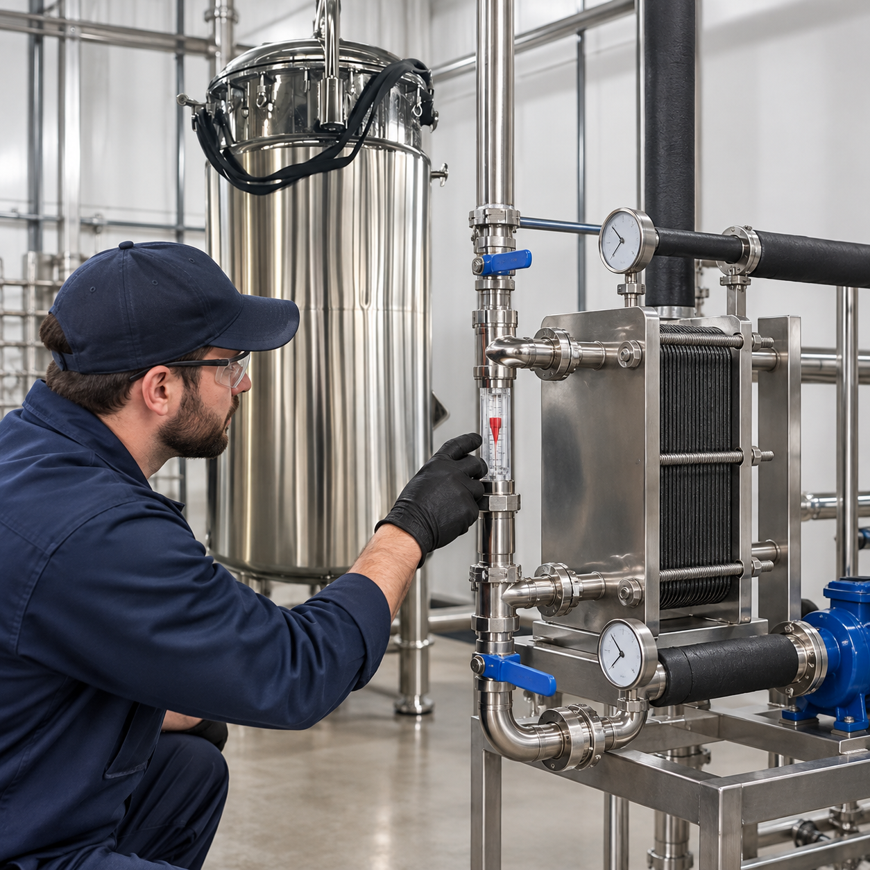
A vessel jacket gives a compact, closed heat-transfer surface and often suits moderate duties, but its effective area is tied to the vessel geometry. An internal coil can add area, yet it occupies process space and creates cleaning and inspection questions. An external loop with a plate heat exchanger can offer accessible area and strong control, but it introduces a circulation pump, extra piping and a new sterile or hygienic boundary. The selection depends on process sensitivity, viscosity, cleanability, available utilities and the acceptable maintenance burden. No arrangement is inherently best for every broth.
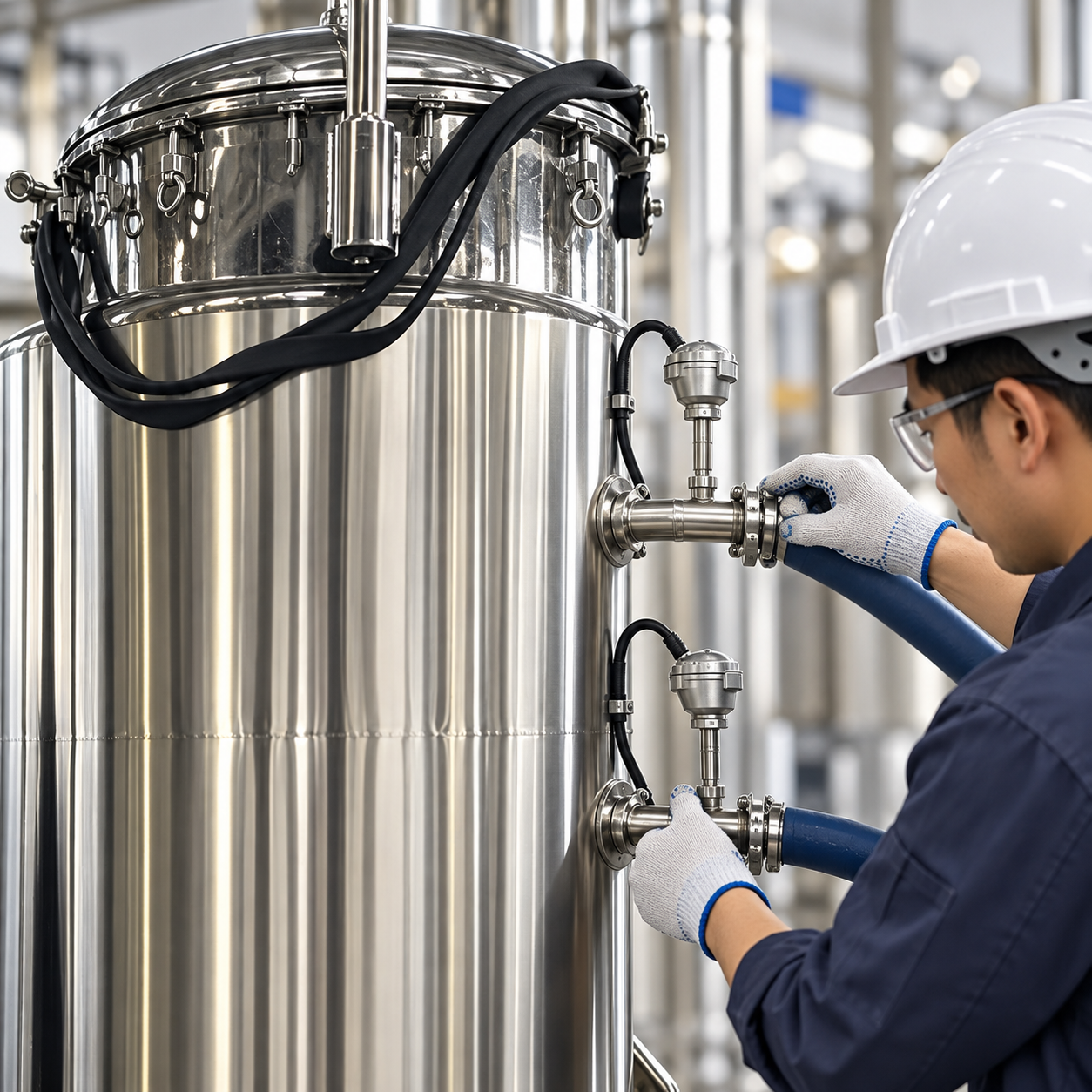
For each option, check the weakest part of the heat path. Poor broth-side mixing can dominate resistance even with cold utility water. A fouled jacket or exchanger reduces U; a partially closed valve or undersized header reduces flow. A control probe placed beside a coolant inlet may see a local temperature rather than the bulk liquid. Request a drawing showing temperature sensors, supply and return nozzles, drain points, isolation valves and service access. The drawing should make it possible to verify that cooling remains available during the highest biological demand.
Finally, test response to a realistic disturbance. Introduce an agreed heat load or use a documented production trend, then observe broth temperature, coolant inlet and outlet temperatures, flow and valve travel. A stable temperature alone may hide a valve that has reached its limit. Record the conditions that produced the result so it can be compared with a hotter utility day or a higher-density batch. This evidence is more useful than a single chiller catalogue number.
Sources and learning video
A peer-reviewed bioprocess review discusses heat transfer alongside mixing and oxygen delivery during scale-up. Research on equipment characterization shows why operating-range measurements matter when transferring processes. The BIPM SI Brochure supports consistent engineering units.

Watch the NPTEL heat-transfer lecture on YouTube. It explains the underlying energy-balance concepts; the process-specific calculation above stands on its own.
Preguntas frecuentes
Is fermenter cooling load the same as chiller nameplate capacity?
No. The required load is the heat removed at the process condition; available utility temperature, flow, piping and heat-transfer area determine what the fermenter can actually remove.
Can motor horsepower be used as agitator heat?
It is an equipment rating, not necessarily actual shaft power. Use a measured or justified operating value and state the assumptions.
Why test more than the end-of-batch condition?
Metabolism, feed and agitation may peak at different times. Check the full batch profile and any specified cooling ramp.